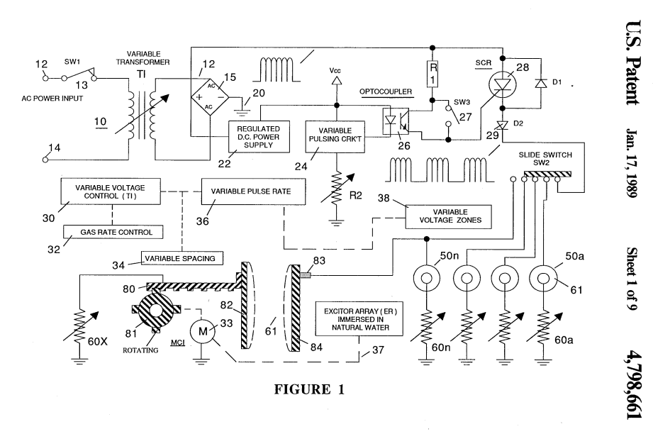
Figure (1)
Figure (1)
How it is written
- (1) 19×
Drawings 1
-
Captioned as this figure · Gas Generator Voltage Control Circuit
On this figure 10
- 15 Rectifier
- 18 Transistor
- 26 Circuit
- 27 Pulse Former
- 28 electronic switch SCR
- 30 Variable Circuit
- 50 Exciter Plates
- 60 Resistor
- 90 Circuit
- 91 Diode
Where it is named · 19
Gas Generator Voltage Control Circuit 19×
-
FIG. 1 is an overall illustration of the present invention in a preferred embodiment; the components shown partly in block schematic and partly pictorially.
-
Referring to the drawings and in particular to FIG. 1, there is illustrated the present invention in its preferred embodiment of a power supply for the aforementioned hydrogen and oxygen gas generator, providing variable amplitude voltage with inhibited electron leakage.
-
The power supply of FIG. 1 includes a variable circuit 30 for varying the amplitude of the rectified voltage by rectifier 15. The variable voltage circuit , in turn, is directly controlled by the gas rate function separately, sequential, and together with the phenomena of a resonant cavity.
-
Returning to the overall circuit of FIG. 1, the uni-polar pulsating d.c. voltage is an improvement in raising the amplitude of the voltage without electron leakage. Unfortunately, it too, has a voltage amplitude limit of 4.0 volts as shown by L-2 of FIG. 8.
-
With reference again to FIG. 1, the variable pulsing circuit comprises an electronic switch SCR 28 operable from one state to another form the opto-coupler timing circuit 26. The operation and of the pulsing of a voltage is within the state of the art.
-
… Accordingly, to achieve the most effective relationship between gas generation and current limiting, the voltage amplitude is interrelated to the pulse repetition rate of the duty pulses in FIG. 1. Also, the rate of production is related to the frequency of the uni-polar d.c. voltage, the frequency then should be interrelated to the duty cycle pulses.
-
The next expediency in the sequence for inhibiting electron leakage is the current inhibitor resister 60 as shown in FIGS. 1 and 5. …
-
With reference to FIGS. 1 and 8, the pulse d.c. volt- age of a repetitive frequency and the duty cycle pulses, together with the serially connected plate exciter techniques in the sequence for limiting the electron leakage is in relation to the positive exciter outer plate. The current inhibitor resistor 60 and the current inhibitor resistor 70/74 are in the negative voltage line connected to the inner plate.
-
With particular reference now to FIG. 5, there is illustrated an alternative embodiment for deriving the uni-polar d.c. voltage pulse of a repetitive frequency—similar to that of FIG. 1. The distinction in the embodiment of FIG. 5 is that the input voltage is a direct current in contrast to the alternating current of FIG. 1.
-
With particular reference now to FIG. 5, there is illustrated an alternative embodiment for deriving the uni-polar d.c. voltage pulse of a repetitive frequency—similar to that of FIG. 1. The distinction in the embodiment of FIG. 5 is that the input voltage is a direct current in contrast to the alternating current of FIG. 1.
-
… The output is similar to that derived from the alternating voltage input of FIG. 1. The d.c. voltage is a constant voltage pulse.
-
Again similar to FIG. 1, there is provided a timed pulsing circuit comprised of a timer 17, switch 19, and transistor 18. Initially, the d.c. pulse voltage is switched on and off, to provide a constant share time duty cycle to the primary winding 42 of the rotating field. In the off period there will be no voltage on the primary winding 42, and hence, no voltage output on the secondary winding 46.
-
The resistor 60 of FIGS. 1 and 5, connected between the exciter plate having the negative voltage applied thereto and ground is an effective current limiter/electron inhibitor. In simple terms the restriction to current flow to the negative plate is a restriction to the flow of current between the pair of plate exciters.
-
The resistor 60 of FIGS. 1 and 5, and especially when taken together with the resistive plate structure of FIG. 7, current is eliminated from the plate exciters.
-
In FIG. 1 there is illustrated an alternative manner of varying the rate of separation of the hydrogen and oxygen gasses from water. As fully disclosed and described in the aforesaid co-pending application Ser. No. 302,807, the spacing between the plate exciters in water is directly related to the rate of separation of the hydrogen and oxygen gasses.
-
The resonant cavity is depicted in FIG. 4 pictorially. It is understood that the exciter plates 50a-50n of FIG. 1 become resonant cavities by matching the distance between the exciters to a pulse frequency of the same wavelength,
-
Referring again to FIG. 6, attention is directed to the resonant cavity depicted therein pictorially. The resonant cavity would be the plate exciter of FIG. 1 or any other plate exciter wherein the frequency of the pulses of the applied voltage is matched in wavelength to the distance between the exciter plates
-
The SCR diode is a duty cycle pulse former much in the same manner as the pulse former 27 of FIG. 1 - The SCR diode 90 is operational in a conventional manner and the diode 91 is a conventional blocking diode. The operation and function of the resonant cavity is much in the same manner as that of FIG. 1 plate exciters 50a-50n.
-
The SCR diode is a duty cycle pulse former much in the same manner as the pulse former 27 of FIG. 1 - The SCR diode 90 is operational in a conventional manner and the diode 91 is a conventional blocking diode. The operation and function of the resonant cavity is much in the same manner as that of FIG. 1 plate exciters 50a-50n.