Figure (4A)
Figure (4A)
How it is written
- (4A) 2×
Drawings 3
-
Captioned as this figure · Gas Generator Voltage Control Circuit
-
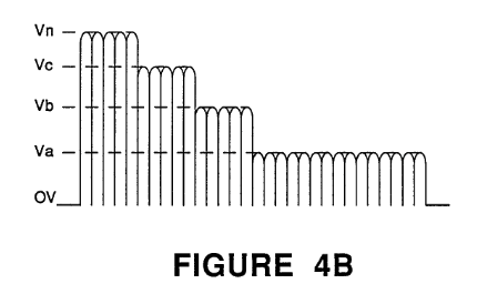
In FIG. 4A and 4B, the frequency of the pulsed d.c. voltage is matched to the distance in wavelengths of the plate exciters. · Gas Generator Voltage Control Circuit
-
In FIG. 4A and 4B, the frequency of the pulsed d.c. voltage is matched to the distance in wavelengths of the plate exciters. · Gas Generator Voltage Control Circuit
Where it is named · 2
Gas Generator Voltage Control Circuit 2×
-
FIG. 4A illustrates the duty cycle as being non-uniform and between gradient levels;
-
In FIG. 4A and 4B, the frequency of the pulsed d.c. voltage is matched to the distance in wavelengths of the plate exciters.