Figure (6)
Figure (6)
How it is written
- (6) 5×
Drawings 1
-
In FIG. 4A and 4B, the frequency of the pulsed d.c. voltage is matched to the distance in wavelengths of the plate exciters. · Gas Generator Voltage Control Circuit
On this figure 1
Where it is named · 5
Gas Generator Voltage Control Circuit 5×
-
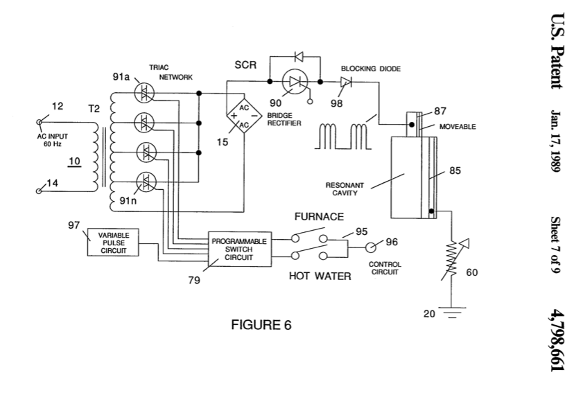
FIG. 6 is a schematic of the circuitry for programming the varying levels of voltage to practical applications.
-
… As will be understood below relative to the programming circuit of FIG. 6, the time period of the pulses may be varied periodically or apericdically, the duration of the on/off period may be varied, the gradient level of the on/off pulses may be varied, and all of the above may be interrelated into a sequence of duty pulses with the varying conditions all as shown in FIGS. …
-
In FIG. 6, there is illustrated the resonate cavity of my aforesaid co-pending patent application Ser. …
-
Referring again to FIG. 6, attention is directed to the resonant cavity depicted therein pictorially. The resonant cavity would be the plate exciter of FIG. 1 or any other plate exciter wherein the frequency of the pulses of the applied voltage is matched in wavelength to the distance between the exciter plates
-
In FIG. 6, the programmable switch circuit 79 is for variable inputs to a utilitarian device, such as the aforesaid furnace or the automobile hydrogen engine dis- closed and claimed in my co-pending patent application Ser. No. 478,207. In the practical working embodiments the demand may be for hot water, heat, singly or together; and in the automobile the rate of acceleration; or simply the control of the flame size.