Figure (2)
Figure (2)
How it is written
- (2) 4×
Drawings 2
-
Captioned as this figure · Gas Generator Voltage Control Circuit
-
Captioned as this figure · Gas Generator Voltage Control Circuit
Where it is named · 4
Gas Generator Voltage Control Circuit 4×
-
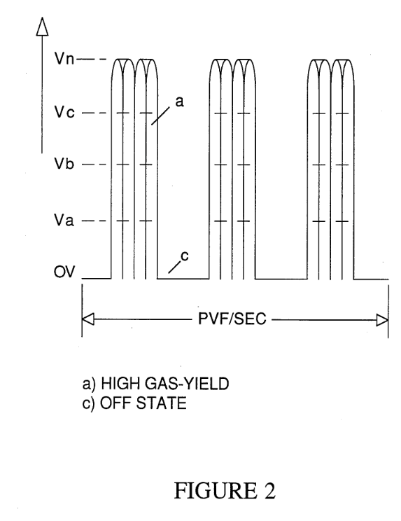
FIG. 2 is a first waveform illustrating the uni-polar pulse d.c voltage of repetitive frequency with a uniform duty cycle.
-
To further restrict current flow with amplitude voltages above the level L-2 of FIG. 8, electron leakage is inhibited from the exciter plate having the negative voltage applied thereto, by varying the duty cycle pulse of the pulsed d.c. voltages as shown FIGS. 2, 3, and 8.
-
The pulsing of the pulsed d.c. voltage, as shown by the waveform of FIG. 2, comprises switching, via trig- ger circuit 26, the pulsed d.c. …
-
With reference again to FIGS. 2, 3, 4, 4A, 4B, 4C, and 4D, the waveforms illustrated therein depict the several variations of the pulsed d.c. …