Figure (4)
Figure (4)
How it is written
- (4) 5×
Drawings 4
-
Captioned as this figure · Gas Generator Voltage Control Circuit
-
In FIG. 4 and 4C, the duty cycle pulses are matched in pulse repetition rate to the plate distance. · Gas Generator Voltage Control Circuit
-
In FIG. 4 and 4C, the duty cycle pulses are matched in pulse repetition rate to the plate distance. · Gas Generator Voltage Control Circuit
-
Captioned as this figure · Gas Generator Voltage Control Circuit
Where it is named · 5
Gas Generator Voltage Control Circuit 5×
-
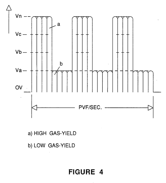
FIG. 4 illustrates the uni-polar pulse voltage of a repetitive frequency having a uniform duty cycle from a low gradient level to high gradient level;
-
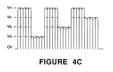
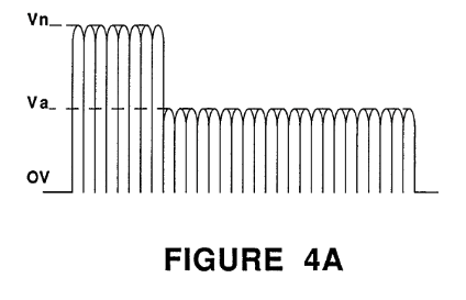
… 6, the time period of the pulses may be varied periodically or apericdically, the duration of the on/off period may be varied, the gradient level of the on/off pulses may be varied, and all of the above may be interrelated into a sequence of duty pulses with the varying conditions all as shown in FIGS. 4, 4A, 4B, and 4C.
-
The resonant cavity is depicted in FIG. 4 pictorially. It is understood that the exciter plates 50a-50n of FIG. 1 become resonant cavities by matching the distance between the exciters to a pulse frequency of the same wavelength,
-
In FIG. 4 and 4C, the duty cycle pulses are matched in pulse repetition rate to the plate distance.
-
The waveform is shown in FIG. 4. The lower level amplitude Va is not 0V the zero level; the amplitude level Va is sufficient to maintain resonance with a matched repetition rate of the duty cycle pulses.