Figure (5)
Figure (5)
How it is written
- (5) 5×
Drawings 1
-
Captioned as this figure · Gas Generator Voltage Control Circuit
On this figure 1
Where it is named · 5
Gas Generator Voltage Control Circuit 5×
-
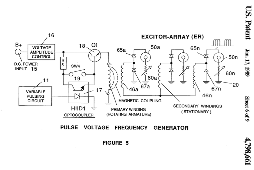
FIG. 5 illustrates partly schematic and partly in block the pulse frequency generator from a direct current voltage source.
-
With particular reference now to FIG. 5, there is illustrated an alternative embodiment for deriving the uni-polar d.c. voltage pulse of a repetitive frequency—similar to that of FIG. 1. The distinction in the embodiment of FIG. 5 is that the input voltage is a direct current in contrast to the alternating current of FIG. 1.
-
With particular reference now to FIG. 5, there is illustrated an alternative embodiment for deriving the uni-polar d.c. voltage pulse of a repetitive frequency—similar to that of FIG. 1. The distinction in the embodiment of FIG. 5 is that the input voltage is a direct current in contrast to the alternating current of FIG. 1.
-
In operation of the circuit of FIG. 5, a low voltage, such as from a battery, is applied to the primary wind- ing to the circuit of a rotating field. The primary wind- ing 42 being the rotating field has it opposite end connected to ground. As the field of the primary winding 42 rotates, there is induced three pulses at the output of each of the three secondary windings 46a 468, and 46c.
-
The circuit of FIG. 5 is especially economical in that extremely low amplitude voltages (0-5 volts) is applied to the primary 42. …