Figure (8)
Figure (8)
How it is written
- (8) 10×
Drawings 2
-
Captioned as this figure · Gas Generator Voltage Control Circuit
-
Captioned as this figure · Gas Generator Voltage Control Circuit
Where it is named · 10
Gas Generator Voltage Control Circuit 10×
-
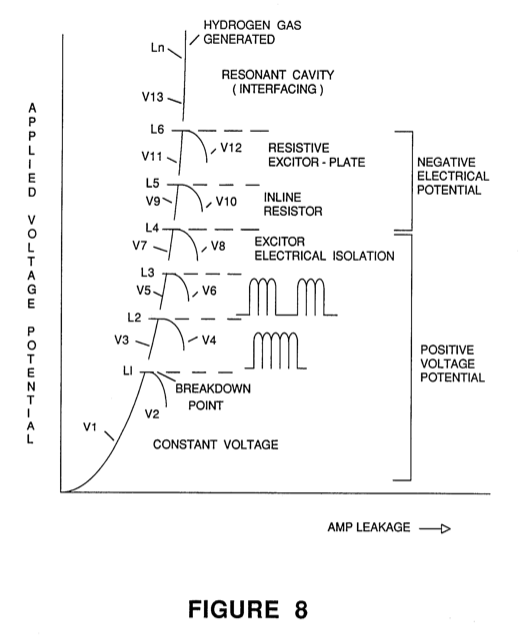
FIG. 8 is a graphical illustration of the varying limitations of voltage amplitude for inhibiting electron leakage.
-
As stated, a voltage with an amplitude below the minimum level for example, with a given size apparatus, 2.5 volts (L-1 of FIG. 8) when applied to the pair of plate exciters, is insufficient amplitude to force the electrons to leak from the negative plate exciter. …
-
Above the minimum level (L-1 of FIG. 8) of amplitude, the applied voltage will have a sufficient force to agitate and cause movement of the electrons around the negative plate exciter. As a consequence electron leakage would take place.
-
Referring to FIG. 8, there is illustrated an appreciation of the significance of electron leakage.
-
Returning to the overall circuit of FIG. 1, the uni-polar pulsating d.c. voltage is an improvement in raising the amplitude of the voltage without electron leakage. Unfortunately, it too, has a voltage amplitude limit of 4.0 volts as shown by L-2 of FIG. 8.
-
To further restrict current flow with amplitude voltages above the level L-2 of FIG. 8, electron leakage is inhibited from the exciter plate having the negative voltage applied thereto, by varying the duty cycle pulse of the pulsed d.c. voltages as shown FIGS. 2, 3, and 8.
-
The dual pulses comprised of the frequency repetitive pulses and the duty cycle pulses similarly to the previous configuration. The amplitude is effective to increase the output gas generation with an upper limit of 5.5 volts, in this instance L-3 of FIG. 8.
-
With reference to FIG. 8 again, it is seen that although the serially connected exciter plates do permit a higher amplitude of voltage to be applied, it too, has a limitation L-4 of 7 volts.
-
The electron leakage resistor will again raise the upper limit of 8.5 volts amplitude before breakdown as shown at L-5 of FIG. 8. In the generation of the hydro- gen and oxygen gasses to an infinite limit, as yet not fully appreciated, the upper level of amplitude of the voltage is removed with the utilization of the electron inhibitor of FIG. 7.
-
… In a smaller structure, the voltage levels of FIG. 8 were utilized.