(20)
Chamber
Also written gas generation device
Where it is first named
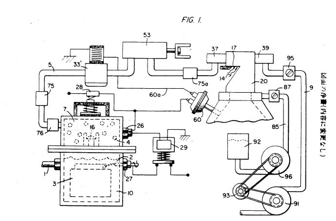
As explained with reference to figure 2, the hydrogen gas is sent through pipe 5, and the combustible gas is sent through pipe 9. Then, the mixed gas is conveyed to the mixing chamber 20 via the ejector or other mixing mechanisms, where atmospheric air intake section 14 is also set up.
How it is written
- (chamber 20) 9×
- (gas generation device 20) 1×
Drawings 6
-
Carries this number · ydrogen Gas Injection Apparatus for Internal Combustion Engine
-
Carries this number · ydrogen Gas Injection Apparatus for Internal Combustion Engine
-
Carries this number · ydrogen Gas Injection Apparatus for Internal Combustion Engine
-
Carries this number · ydrogen Gas Injection Apparatus for Internal Combustion Engine
-
Carries this number · ydrogen Gas Injection Apparatus for Internal Combustion Engine
-
Carries this number · ydrogen Gas Injection Apparatus for Internal Combustion Engine
Where it is named · 10
ydrogen Gas Injection Apparatus for Internal Combustion Engine 10×
-
chamber (chamber 20)
As explained with reference to figure 2, the hydrogen gas is sent through pipe 5, and the combustible gas is sent through pipe 9. Then, the mixed gas is conveyed to the mixing chamber 20 via the ejector or other mixing mechanisms, where atmospheric air intake section 14 is also set up.
-
chamber (chamber 20)
The hydrogen gas passes through nozzle 11, through spray 16, and reaches the trap area 46 within the mixing chamber 20. Nozzle 11 is equipped with a small hole at the opening of the cooling device 37 to prevent any sparks from causing a flashback.
-
chamber (chamber 20)
The non-combustible gas passes through nozzle 13 and is injected into the trap area 47 in the mixing chamber 20 as jet spray 17. The ignition device 39 works in conjunction with the emergency valve 37.
-
chamber (chamber 20)
Gas flows from chamber 43 to chamber 47. In the diagram, the air volume control device for regulating the amount of air sent to chamber 20 is illustrated. …
-
chamber (chamber 20)
As shown in Figure 6, when hydrogen gas passes through chamber 20 at high pressure, any water collected at filter 34 will be discharged through line 36, and the remaining hydrogen gas will be safely released into the atmosphere.
-
chamber (chamber 20)
… The air passes through filter 91 attached to sections 14b and 14c and then flows into the intake section 14d of the mixing chamber 20. …
-
chamber (chamber 20)
… Water flows through pipe 5 and passes through cooling device 37 before entering the mixing chamber 20. The non-combustible gas from the combustion chamber passes through cooling device 39 and then enters the mixing chamber 20.
-
chamber (chamber 20)
… The non-combustible gas from the combustion chamber passes through cooling device 39 and then enters the mixing chamber 20.
-
chamber (chamber 20)
The oil supply valve 85 regulates the flow of the oil atomizer, delivering it into chamber 20 for combustion.
-
gas generation device (gas generation device 20)
1... Water supply source 3... Plate (injector plate) 4... Hydrogen gas 7... Hydrogen storage area 10... Hydrogen gas generation device 20... Gas mixing chamber