Figure (3)
Figure (3)
How it is written
- (3) 11×
Drawings 2
-
Page 10 · Electrical Pulse Generator
-
Page 9 · Electrical Pulse Generator
On this figure 13
- 10 Stationary Disc
- 13 Electromagnets
- 15 Electromagnets
- 22 Pully
- 24 Shaft
- 26 Set Washer
- 30 Ring
- 31 Simple Wire
- 37 Terminals
- 42 Terminal
- 44 Disc
- 50 Terminal
- 52 Terminal
Where it is named · 11
Electrical Pulse Generator 11×
-
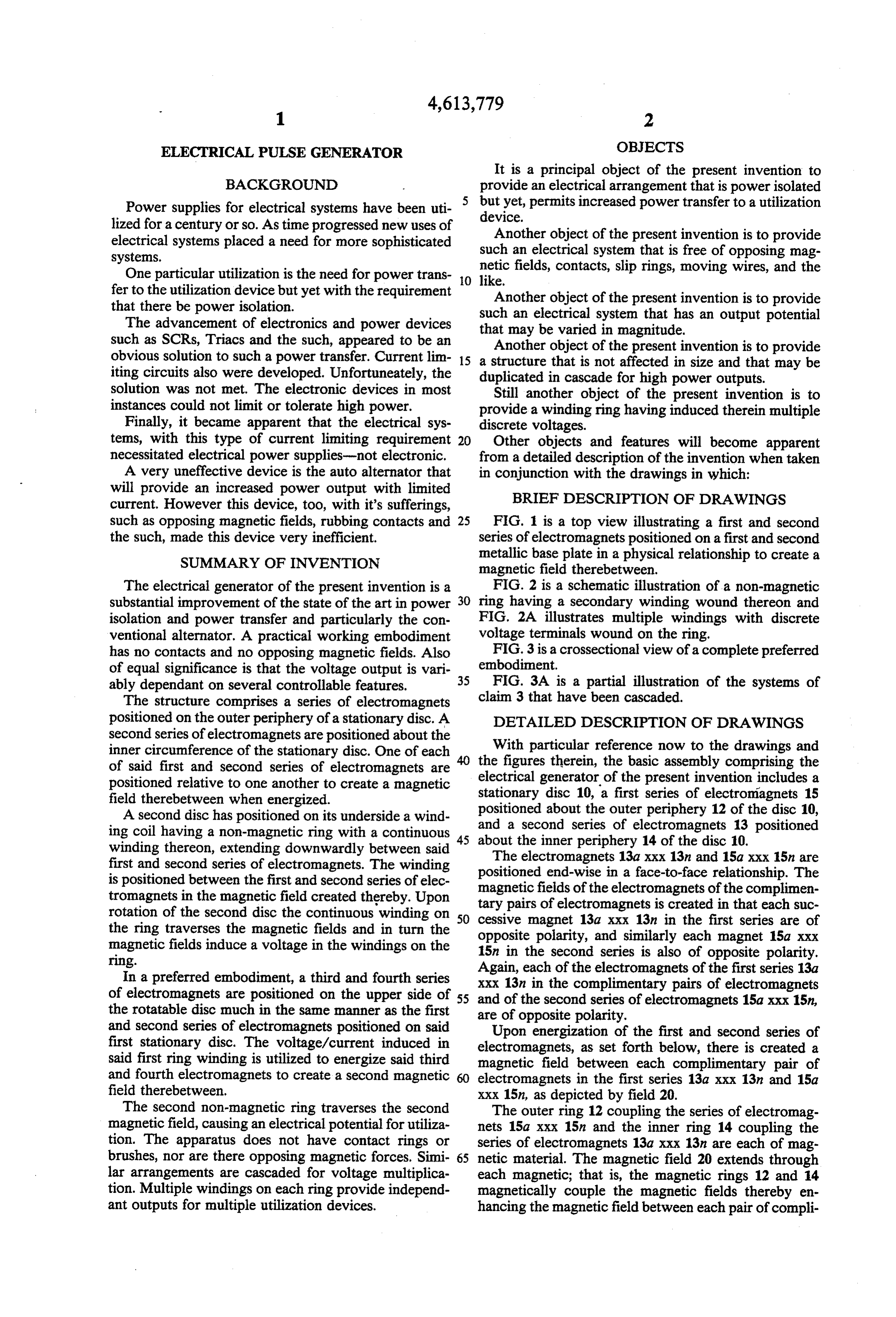
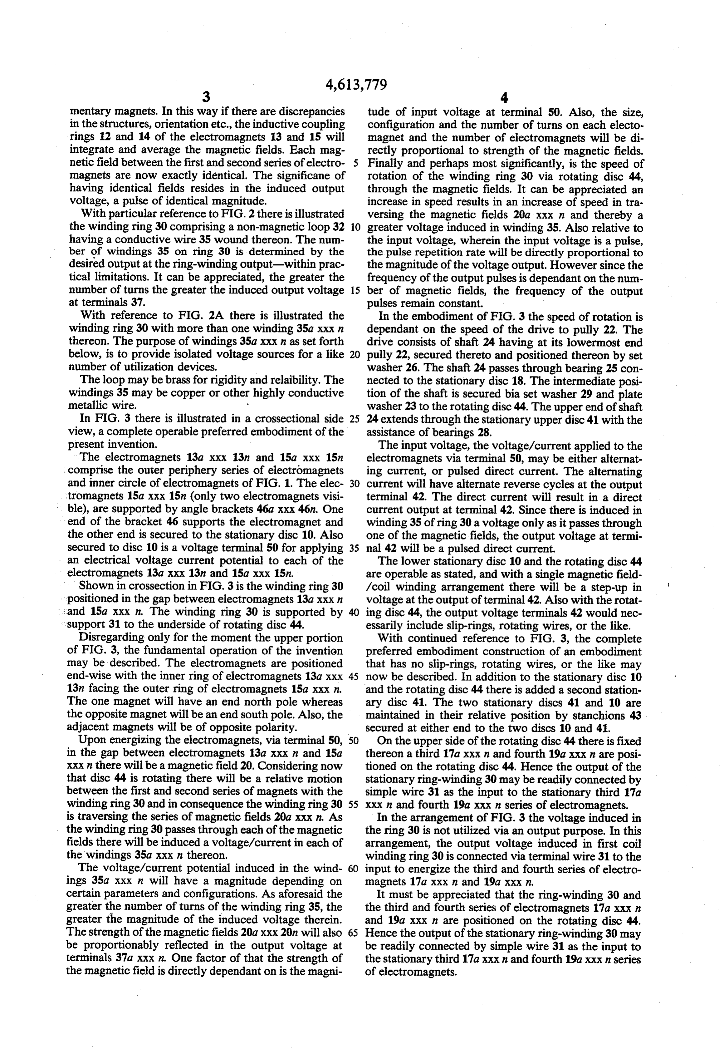
FIG. 3 is a crossectional view of a complete preferred embodiment.
-
In FIG. 3 there is illustrated in a crossectional side view, a complete operable preferred embodiment of the present invention.
-
… Shown in crossection in FIG. 3 is the winding ring 30 positioned in the gap between electromagnets 13a xxx and 15a@ xxx n. The winding ring 30 is supported by �39;support 31 to the underside of rotating disc 44.
-
Disregarding only for the moment the upper portion of FIG. 3, the fundamental operation of the invention may be described. …
-
In the embodiment of FIG. 3 the speed of rotation is dependant on the speed of the drive to pully 22. …
-
With continued reference to FIG. 3, the complete preferred embodiment construction of an embodiment that has no slip-rings, rotating wires, or the like may now be described. In addition to the stationary disc 10
-
In the arrangement.of FIG. 3 the voltage induced in the ring 30 is not utilized via an output purpose. In this arrangement, the output voltage induced in first coil winding ring 30 is connected via terminal wire 31 to the input to energize the third and fourth series of electromagnets 17a xxx n and 19a xxx n.
-
In the embodiment of FIG. 3 there are a like number of turns on the winding coils equal to the number of devices. One each output 37a xxx n, at its respective terminal is connected a discrete utilitarian device.
-
In the embodiment of FIG. 3 there is shown output at terminal 42. This terminal is for a single phase output. In those instances, wherein there are multiple phase outputs terminal 52 shall comprise an equal number of boltage terminals.
-
With continued reference to FIG. 3 and now FIG. 3A, it can be appreciated any practical number of series of electromagnets and winding rings may be added in cascade for multiple increases in power, Since each complimentary unit is a voltage amplification in itself each additional cascaded arrangement will provide a greater voltage at a geometrical ratio—not arithmetical.
-
In the embodiment of FIG. 3, in the lower portion its electromagnets are fixed and the winding is moved. Whereas in the upper portion the winding is fixed and the electromagnets are moved. It can be appreciated that the essential concern is that there be a relative motion between electromagnets and the winding ring. That which is fixed and that which is moving is irrelevent. Either or both can be moving.