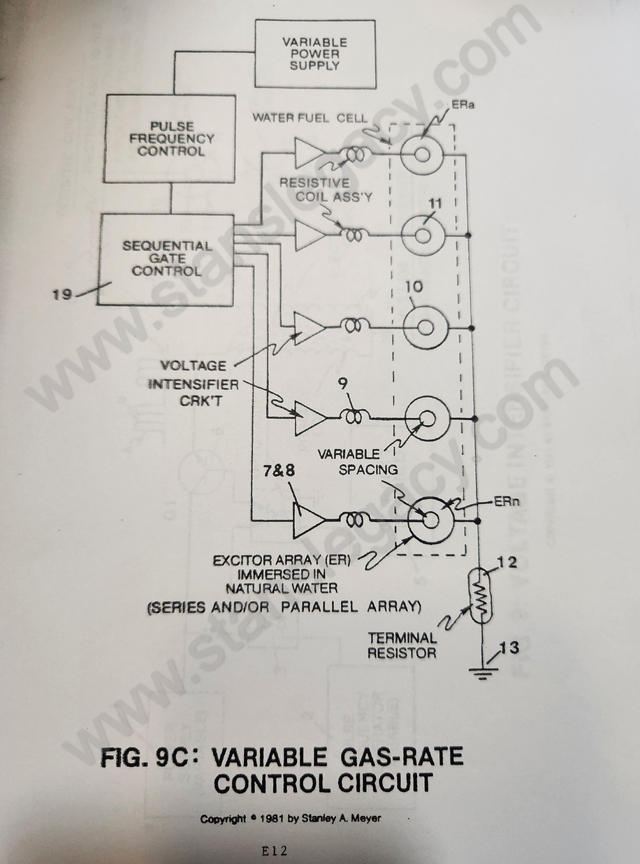
Figure (9C)
Variable Gas-rate F
How it is written
- (9C) 3×
Drawings 1
-
Circuit Stage: (6) as to (7) (8) (9) (10) as of Figure 9C. · Voltage Attenuation Circuit
On this figure 3
Where it is named · 3
Voltage Attenuation Circuit 3×
-
b) Said voltage chambers are relatively "small" or "tiny" in size and can be arranged in parallel or series array, as illustrated in Figure 9C, or stacked in series relationship (exit port to inlet port) for "compounding gas production" (inducing particle impact into said voltage process), as illustrated in Figure 9E.
-
Circuit Stage: (6) as to (7) (8) (9) (10) as of Figure 9C.
-
To extend gas production beyond the limits of a single excitor array (10) (and voltage zones), simply add more excitor array (ER as to 10) to said gas producing process, as shown in Figure 9C.