(10)
Excitor-Array
Also written Circuit Stage · excitor array · voltage zones · fuel cell
Where it is first named
To establish and set up voltage zones (10) of opposite polarity in natural water without inducing chemical oxidation.
How it is written
- (10) 10×
- (ER as to 10) 1× with (ER)
Drawings 6
-
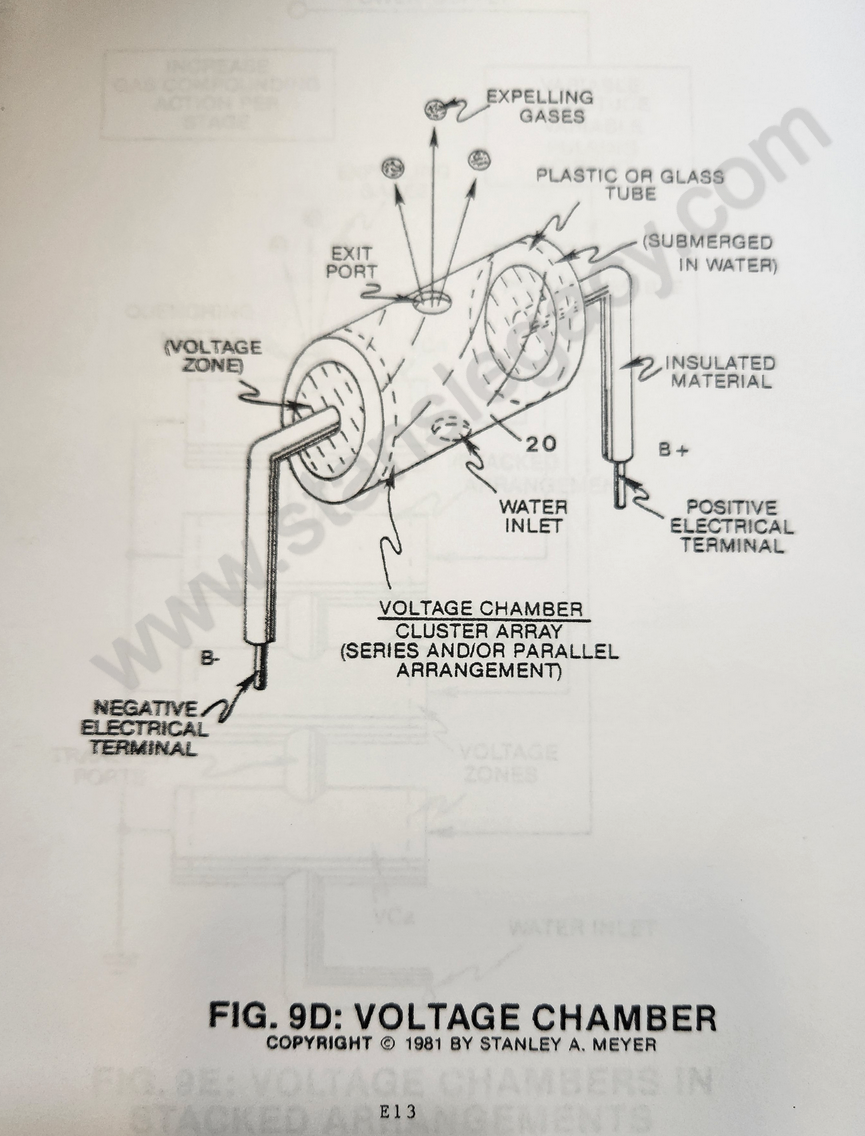
Circuit Stage: (10) as to (20 of Figure 9D)** · Voltage Attenuation Circuit
-
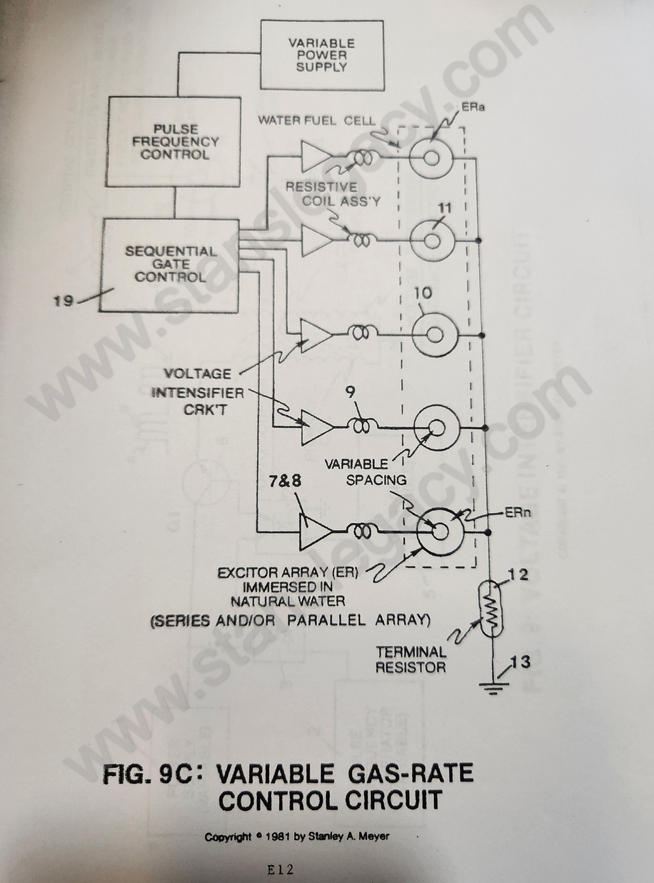
Circuit Stage: (6) as to (7) (8) (9) (10) as of Figure 9C. · Voltage Attenuation Circuit
-
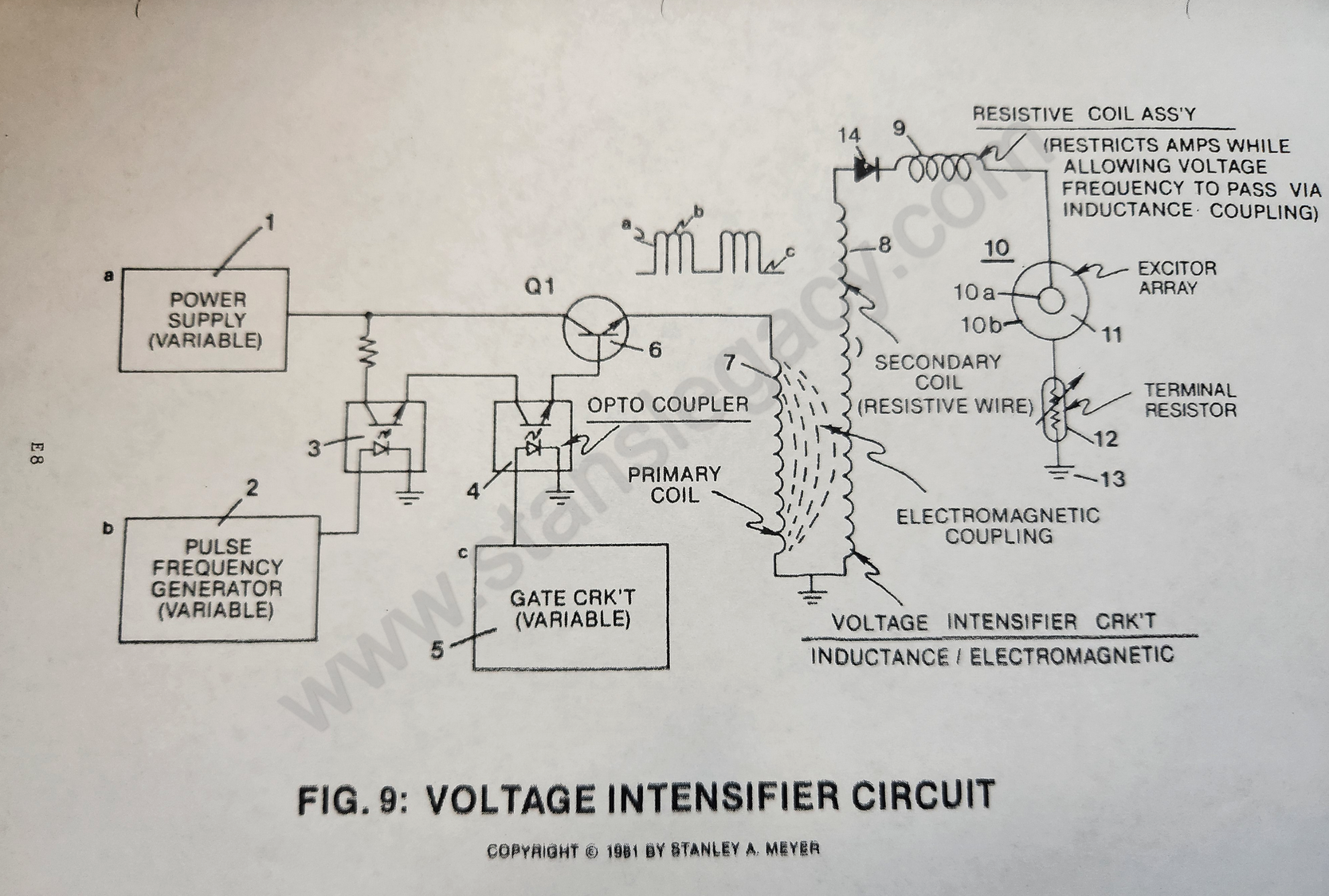
Circuit Stage: (7) (8), (14), (9), (10) as to (11), (10B), (12) and (13). · Voltage Attenuation Circuit
-
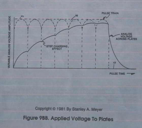
As a result, a step-charging effect (voltage), as illustrated in Figure 9BB, is applied across the fuel cell (10). · Voltage Attenuation Circuit
-
d) To restrict amps still further by using resistive wire to form said pickup winding, see Figure 9XF and Figure 9XG. · Voltage Attenuation Circuit
-
Purpose: To interface said pulsing circuit (Figure 9) with another type of power supply. · Voltage Attenuation Circuit
Where it is named · 11
Voltage Attenuation Circuit 11×
-
voltage zones (10)
To establish and set up voltage zones (10) of opposite polarity in natural water without inducing chemical oxidation.
-
Circuit Stage: (9) as to (10)
-
Circuit Stage: (6) as to (7) (8) (9) (10) as of Figure 9C.
-
excitor array (10)
To extend gas production beyond the limits of a single excitor array (10) (and voltage zones), simply add more excitor array (ER as to 10) to said gas producing process, as shown in Figure 9C.
-
To extend gas production beyond the limits of a single excitor array (10) (and voltage zones), simply add more excitor array (ER as to 10) to said gas producing process, as shown in Figure 9C.
-
excitor-array (10)
Each excitor-array (10) is connected to the same circuit with said voltage intensifier circuits (7) (8) and (9), which, in turn, are sequentially pulsed (19) to minimize power loss during gas production.
-
excitor-array (10)
By variable pulsing circuit (1) (2) (3) (4) (5) as to (6) remains under power, however additional excitor-array (10) as herein described is added, power loss or drainage is held to a minimum (ninth-stage to amp restriction).
-
excitor-array (10)
Terminal resistor (12 of Figure 9) is affixed to said excitor-array (10) on ground side (see Figure 9 again) to prevent counter electron deflection or movement within said interfacing circuit (8 as to 9).
-
fuel cell (10)
As a result, a step-charging effect (voltage), as illustrated in Figure 9BB, is applied across the fuel cell (10).