(12)
Terminal resistor
Also written series resonant charging choke-coil
Where it is first named
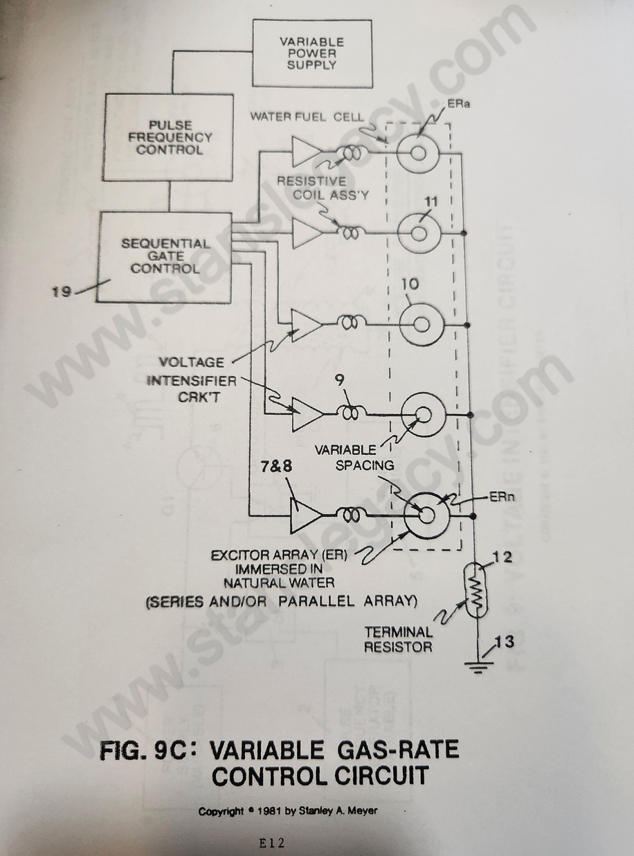
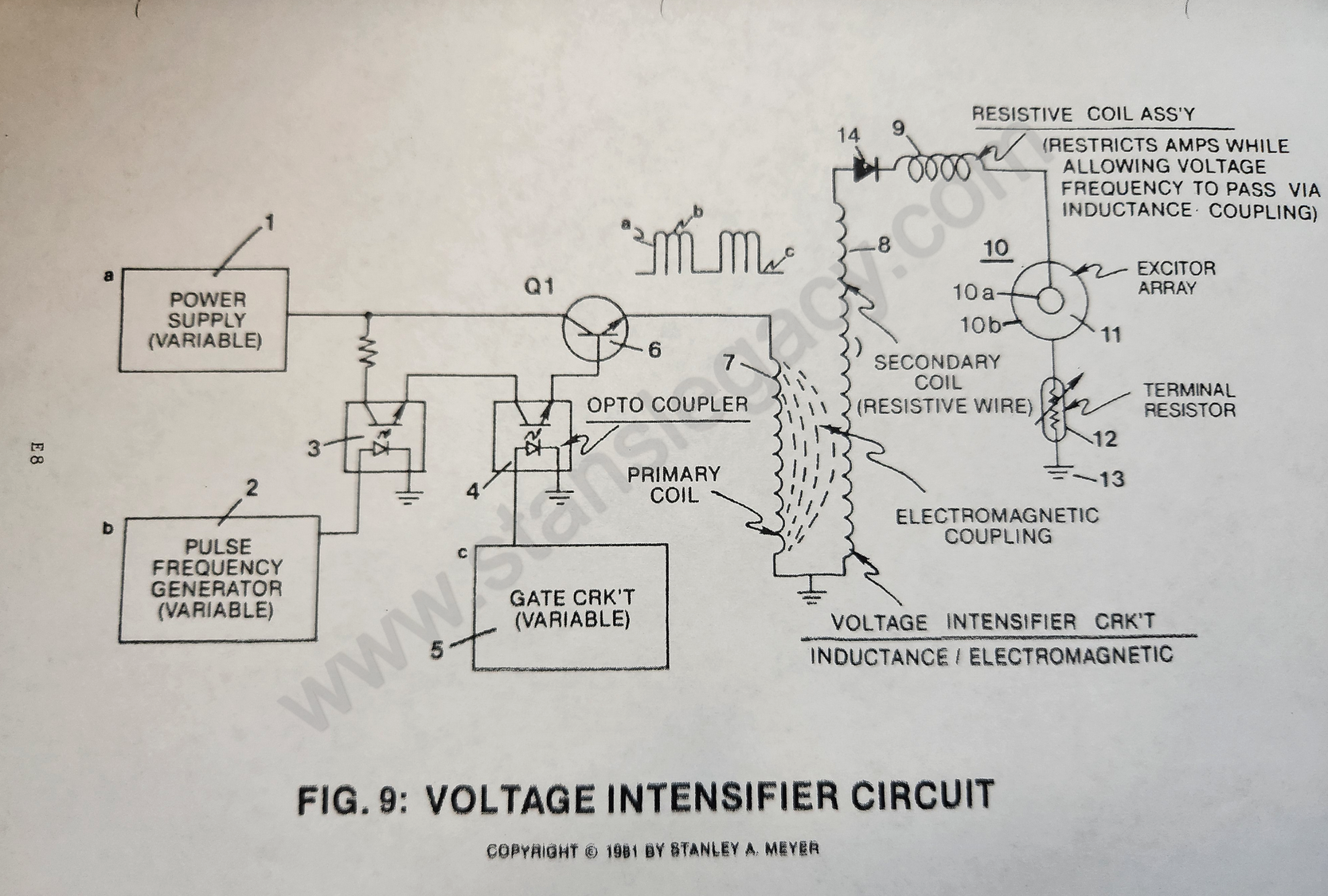
Terminal resistor (12 of Figure 9) is affixed to said excitor-array (10) on ground side (see Figure 9 again) to prevent counter electron deflection or movement within said interfacing circuit (8 as to 9).
How it is written
- (12) 6×
- (12 of Figure 9) 1× with Figure (9) Variable Amplitude Unipolar Pulse Voltage Frequency Super Im- Posed Onto An 50
Drawings 5
-
Circuit Stage: (6) as to (7) (8) (9) (10) as of Figure 9C. · Voltage Attenuation Circuit
-
Circuit Stage: (7) (8), (14), (9), (10) as to (11), (10B), (12) and (13). · Voltage Attenuation Circuit
-
d) To restrict amps still further by using resistive wire to form said pickup winding, see Figure 9XF and Figure 9XG. · Voltage Attenuation Circuit
-
d) To restrict amps still further by using resistive wire to form said pickup winding, see Figure 9XF and Figure 9XG. · Voltage Attenuation Circuit
-
Purpose: To interface said pulsing circuit (Figure 9) with another type of power supply. · Voltage Attenuation Circuit
Where it is named · 7
Voltage Attenuation Circuit 7×
-
terminal resistor (12)
Said terminal resistor (12) is composed of resistive wire wrapped in a coil configuration, taking the shape of said bypass coil (9).
-
terminal resistor (12)
Said bypass coil (9) and said terminal resistor (12) are the same in likeness.
-
terminal resistor (12)
An adjustable terminal lead (wiper arm) is affixed, however, to said terminal resistor (12).
-
terminal resistor (12)
Said terminal resistor (12) can be adjustable to help "tune-in" gas production.
-
series resonant charging choke-coil (12)
The circuit is then tuned to match the resonant characteristic of the total system by adjusting the pulse frequency generator (2) and the series resonant charging choke-coil (12).