Figure (9)
Variable Amplitude Unipolar Pulse Voltage Frequency Super Im- Posed Onto An 50
Also written Voltage Intensifier Circuit Copyaight
How it is written
- (9) 13×
- (12 of Figure 9) 1× with (12) Terminal resistor
- (9 of Figure 9) 1× with (9) Bypass Coil
Drawings 2
-
Circuit Stage: (7) (8), (14), (9), (10) as to (11), (10B), (12) and (13). · Voltage Attenuation Circuit
-
Purpose: To interface said pulsing circuit (Figure 9) with another type of power supply. · Voltage Attenuation Circuit
On this figure 9
- 1 Power Supply Voltage
- 4 Optocoupler
- 8 Secondary Coil
- 9 Bypass Coil
- 9B Pulse Voltage Waveform
- 10 Excitor-Array
- 12 Terminal resistor
- 23 Pulsating Electromagnetic Fields
- 24 Pickup Coils
Where it is named · 15
Voltage Attenuation Circuit 15×
-
Purpose: (See (1) of Figure 9)
-
Circuit Stage: (1) (2) as to (3) of Figure 9
-
Circuit Stage: (4) (5) as to (6) of Figure 9.
-
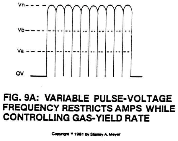
As power transistor Q1 is actuated to produce variable waveform (9B), the output wave form (9B) is now superimposed onto a primary coil wrap around a secondary coil of greater size (more turns of wire), forming a voltage intensifier transformer, see Figure 9.
-
Purpose: To restrict amp flow while allowing voltage potential to pass through said bypass coil (9 of Figure 9) via electromagnetic induction coupling.
-
Purpose: To restrict amp flow while allowing voltage potential to pass through said bypass coil (9 of Figure 9) via electromagnetic induction coupling.
-
Due to the skin-effect phenomenon, voltage forms across said plates of Figure 9, forming voltage zones of opposite polarity. Switching off said voltage pulse eliminates said voltage zones.
-
Terminal resistor (12 of Figure 9) is affixed to said excitor-array (10) on ground side (see Figure 9 again) to prevent counter electron deflection or movement within said interfacing circuit (8 as to 9).
-
Terminal resistor (12 of Figure 9) is affixed to said excitor-array (10) on ground side (see Figure 9 again) to prevent counter electron deflection or movement within said interfacing circuit (8 as to 9).
-
Terminal resistor (12 of Figure 9) is affixed to said excitor-array (10) on ground side (see Figure 9 again) to prevent counter electron deflection or movement within said interfacing circuit (8 as to 9).
-
The electrical control circuit used to start and control the gas generation process is shown in the schematic diagram of Figure 9.
-
The voltage intensifier circuit (Figure 9) converts the variable DC supply voltage (1) into a continuous high-frequency positive unipolar signal (Figure 9B) to control the variable duty cycle pulse train (Figure 9B) to control the power supply (1).
-
The water fuel cell is filled with water (10 & 11), the excitor plates adjusted for the correct distance and volume, then connected to the voltage intensifier circuit (Figure 9).
-
Purpose: To interface said pulsing circuit (Figure 9) with another type of power supply.