Figure (9B)
Figure (9B)
How it is written
- (9B) 6×
Drawings 1
-
Purpose: To interface said pulsing circuit (Figure 9) with another type of power supply. · Voltage Attenuation Circuit
On this figure 6
- 1 Power Supply Voltage
- 4 Optocoupler
- 5 Variable Gate Control Circuit
- 9 Bypass Coil
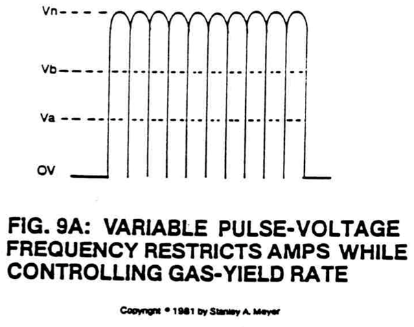
- 9A Pulse Voltage Frequency
- 10A Stainless Steel Excitor Plates
Where it is named · 6
Voltage Attenuation Circuit 6×
-
Optocoupler (4) is another photoisolation switch that when triggered by variable gate circuit (5) (a second variable triggering circuit) causes said pulse voltage frequency wave form (9A) to be altered as shown in Figure 9B.
-
The pulse voltage waveform (mirror imaged of Figure 9B) developed at said bypass coil (9) output lead is now transferred to stainless steel plates (excitor array) submerged in natural water.
-
The voltage intensifier circuit (Figure 9) converts the variable DC supply voltage (1) into a continuous high-frequency positive unipolar signal (Figure 9B) to control the variable duty cycle pulse train (Figure 9B) to control the power supply (1).
-
The voltage intensifier circuit (Figure 9) converts the variable DC supply voltage (1) into a continuous high-frequency positive unipolar signal (Figure 9B) to control the variable duty cycle pulse train (Figure 9B) to control the power supply (1).
-
The high voltage pulse train (16 of Figure 9B) is then coupled to the stainless steel excitor plates (10A) submerged in water, producing gas output.
-
By way of transformer-action (electromagnetic coupling), the step-charging effect of Figure 9B enhances the gas-yield by maintaining a stable voltage zone.