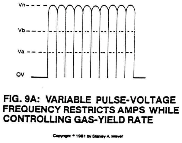
Figure (9A)
Variable Pulse-voltage Frequency Restricts Amps While Controlling Gas-yield Rate
How it is written
- (9A) 7×
Drawings 1
-
Captioned as this figure · Voltage Attenuation Circuit
On this figure 7
- 1 Power Supply Voltage
- 2 Pulse Frequency Generator Circuit
- 3 Optocoupler
- 9A Pulse Voltage Frequency
- 16 On-Time
- 17 Off-Time
- ER —
Where it is named · 7
Voltage Attenuation Circuit 7×
-
Optocoupler (3) is a photosolation switch that when triggered by pulse frequency generator circuit (2) causes power supply voltage (1) to be attenuated as per Figure 9A, setting up a pulse voltage frequency.
-
Phototransistor of said optocoupler (3) now allows said pulse voltage frequency amplitude (Va-Vn of Figure 9A) to be varied from less than one volt to over 110 volts via said variable power supply (1).
-
The variable pulse voltage frequency (9A) is adjusted to keep amp flow restricted during first-stage to amp restriction by allowing said voltage amplitude (Va-Vn of Figure 9A).
-
The variable pulse voltage frequency amplitude (Va-Vn of Figure 9A) is directly related to hydrogen gas production on demand (second stage to voltage attenuation).
-
To switch off and on said generated pulse voltage frequency (9A) at a variable time rate while maintaining said voltage amplitude control (Va-Vn of Figure 9A).
-
The voltage amplitude (Va-Vn of Figure 9A) remains variable as to gas needs.