(1)
Power Supply Voltage
Also written variable DC power supply · variable power supply · power supply · variable DC supply voltage · Circuit Stage
Where it is first named
Circuit Stage: (1) (2) as to (3) of Figure 9
How it is written
- (1) 8×
Drawings 4
-
Variable gating circuit (4) (5) as to (6) simply switches off and on said D.C. pulse train, duplicating pulse voltage waveform (9B). · Voltage Attenuation Circuit
-
The figure it sits on · Voltage Attenuation Circuit
-
Circuit Stage: (7) (8), (14), (9), (10) as to (11), (10B), (12) and (13). · Voltage Attenuation Circuit
-
Purpose: To interface said pulsing circuit (Figure 9) with another type of power supply. · Voltage Attenuation Circuit
Where it is named · 8
Voltage Attenuation Circuit 8×
-
power supply voltage (1)
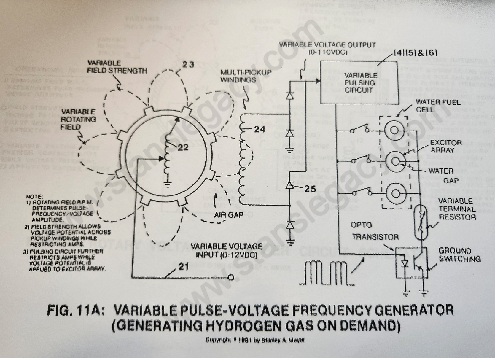
Optocoupler (3) is a photosolation switch that when triggered by pulse frequency generator circuit (2) causes power supply voltage (1) to be attenuated as per Figure 9A, setting up a pulse voltage frequency.
-
variable power supply (1)
Phototransistor of said optocoupler (3) now allows said pulse voltage frequency amplitude (Va-Vn of Figure 9A) to be varied from less than one volt to over 110 volts via said variable power supply (1).
-
power supply voltage (1)
Purpose: To step up power supply voltage (1) while maintaining said variable voltage amplitude (Va-Vn) control, said variable pulse frequency (9A) control, said variable gate (9B) control, and performing a third, fourth, and fifth step to amp restriction.
-
power supply voltage (1)
The step-up voltage amplitude is, however, directly related to power supply voltage (1) and attenuated during gas production.
-
variable DC power supply (1)
The amount of gas output from the water fuel cell is then adjusted by the variable gate control circuit (5) and the level of the variable DC power supply (1).