(9B)
Pulse Voltage Waveform
Also written variable waveform · waveform · output wave form · variable gate
Where it is first named
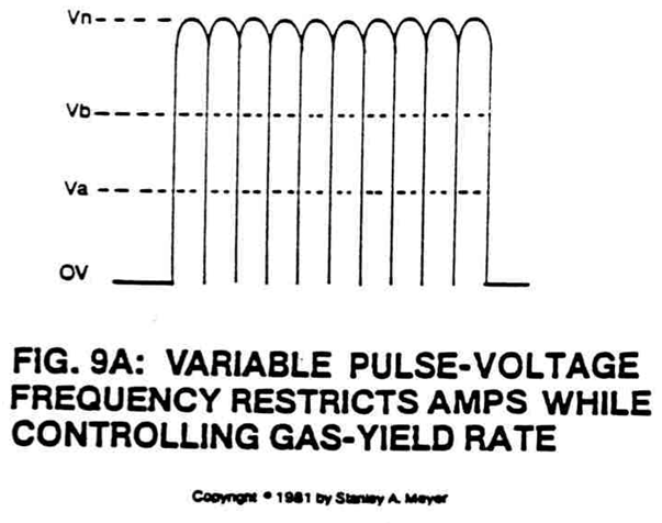
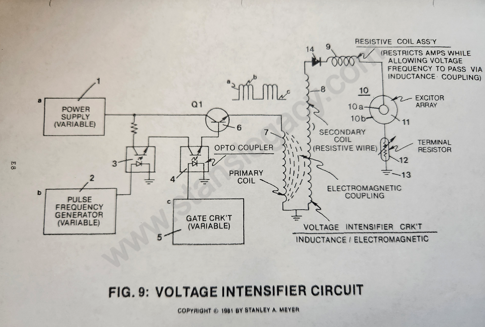
Purpose: To step up power supply voltage (1) while maintaining said variable voltage amplitude (Va-Vn) control, said variable pulse frequency (9A) control, said variable gate (9B) control, and performing a third, fourth, and fifth step to amp restriction.
How it is written
- (9B) 5×
Drawings 2
-
Circuit Stage: (7) (8), (14), (9), (10) as to (11), (10B), (12) and (13). · Voltage Attenuation Circuit
-
Purpose: To interface said pulsing circuit (Figure 9) with another type of power supply. · Voltage Attenuation Circuit
Where it is named · 5
Voltage Attenuation Circuit 5×
-
variable gate (9B)
Purpose: To step up power supply voltage (1) while maintaining said variable voltage amplitude (Va-Vn) control, said variable pulse frequency (9A) control, said variable gate (9B) control, and performing a third, fourth, and fifth step to amp restriction.
-
variable waveform (9B)
As power transistor Q1 is actuated to produce variable waveform (9B), the output wave form (9B) is now superimposed onto a primary coil wrap around a secondary coil of greater size (more turns of wire), forming a voltage intensifier transformer, see Figure 9.
-
output wave form (9B)
As power transistor Q1 is actuated to produce variable waveform (9B), the output wave form (9B) is now superimposed onto a primary coil wrap around a secondary coil of greater size (more turns of wire), forming a voltage intensifier transformer, see Figure 9.
-
waveform (9B)
By way of transformer-action (electromagnetic coupling), said waveform (9B) is now transferred to said secondary coil, performing voltage amplification while said pulse-train remains the same.
-
pulse voltage waveform (9B)
Helps prevent distortion of said pulse voltage waveform (9B) during gas production.