
CA1227094A1 Hydrogen Air & Non-Combustible Gas Mixing Combustion System
PDF Download: SMeyer-CA1227094A1-Hydrogen_Air_&_Non-Combustible_Gas_Mixing_Combustion_System.pdf
.Consumer and Consummation - Corporate Affairs Canada at Corporations Canada
(11) (a) No. 1 227 094
(45) ISSUED 870922
(52) CLASS 123-15 C.R. CL. 158-194
(51) INT. CL. FO2M 21/04ag) ca CANADIAN PATENT «ez
(54) Hydrogen/Air and Non-Combustible Gas Mixing Combustion System
(72) Meyer, Stanley A., U.S.A.
(21) APPLICATION No. 420,889 (22) FILED 830204 No, OF CLAIMS alCanada
DISTRIBUTED BY THE PATENT OF CE, OTTAWA SCA27S [1 1-82) i a
ABSTRACT
An internal combustion engine fuel supply and control that includes apparatus for disassociating hydrogen atoms and oxygen atoms from water and mixing the gas so produced with a non-combustible gas in a predetermined ratio. The gas mixture is mixed with air in suitable proportions and controllably directed to the combustion chamber of the internal combustion engine.
HYDROGEN COMBUSTION SYSTEM
Field of Invention This invention relates to a combustion system and more particularly to one where the combustible gas mixture is hydrogen, oxygen and non-combustible gases.
Illustrations:
 |
 |
 |
 |
 |
Background of Invention
There is disclosed in my co-pending Canadian patent Application Serial No. 420,908, filed February 4, 1983, entitled "A Hydrogen Generator" a generating system converting natural water into hydrogen and oxygen gases.
In that system and method, the hydrogen atoms are disassociated from a water molecule by the application of a non-regulated, non-filtered, low-power, direct current voltage electrical potential applied to two non-oxidizing similar metal plates having water passing therebetween. The action is enhanced by pulsing the non-regulated and non-filtered direct current voltage. Particularly significant with my hydrogen generator disclosed in my co-pending application supra is that the hydrogen/oxygen generated is in a quantity in excess of that necessary for practical utilization.
Further, and equally significant is that the generation of the hydrogen/oxygen is controlled by any one of or combination of several factors:
- varying voltage
- varying pulse rate
- varying spacing between plates
- switching the number of plates
- and changing the plate configuration
The hydrogen/oxygen generation is a demand system; that is, the hydrogen/oxygen is generated only upon the need. Then, the generation is controlled in quantity by the need; such as, accelerator for an automotive device.
In an earlier hydrogen processor, non-combustible gases are controlled in a mixing stage with a combustible gas. The hydrogen processor system utilizes a rotational mechanical gas displacement system to transfer, meter, mix, and pressurize the various gases. In the gas transformation process, ambient air is passed through an open flame gas burner system to eliminate gases and other present substances. Thereafter, the non-combustible gas-mixture is cooled, filtered for impurity removal, and mechanically mixed with a predetermined amount of hydrogen gas. The gas mixture provides the desired burn-rate. The rotational mechanical gas displacement system in that process determines the quantity by volume of combustible gas mixture to be produced.
The above~noted hydrogen processor is a multi-stage system having utility in special applications. The aforementioned co-pending application discloses a very simple and unique hydrogen generator.
Summary of Invention
The system of the present invention in its preferred embodiment is for a combustion system having utility in a mechanical drive system particularly, in one instance, to drive a piston in an automotive device.
The system utilizes the hydrogen generator of my co-pending patent application Serial No. 420,908, for developing hydrogen gas, and other non-combustible gases such as oxygen and nitrogen. The hydrogen gas with the attendant non~combustible gases in a controlled ratio are fed via a line to a controlled air intake system. The combined hydrogen, non-combustible gases, and the air after intermixing are fed to a combustion chamber wherein the mixture is ignited. The exhaust gases of the combustion chamber are returned in a closed loop arrangement to the mixing chamber to provide the non-combustible gases for the mixture. More specifically, generated hydrogen gas is fed to a gas mixing chamber where it is intermixed with non-combustible gases and such gas mixture is then fed to a carburetor (air-mixture) system.
The gas mixture is fed through nozzle means in a jet spray in a chamber and a valve or gate controls the amount of air intake to the jet spray. The gas mixture combines with the air to form a combustible mixture of hydrogen, non-combustible gas, and oxygen. The combustible mixture enters into a combustion chamber conventional in design and comprising a cylinder capable of withstanding high pressure. At the uppermost end of the combustion chamber is a spark plug igniter.
Objects
A principal object of the present invention is to provide a combustion system utilizing gases combined from a source of combustible and non-combustible gases.
Another object of the invention is to provide a combustion system that utilizes hydrogen as the combustible gas and the exhaust of the combustion system as the non-combustible gas.
A further object of the present invention is to provide a combustion system of the foregoing in a mechanical drive system.
Brief Description of the Drawings:
The invention is illustrated by way of example in the accompanying drawings wherein
Figure 1 is a schematic, cross-sectional illustration of the present invention in its preferred embodiment;
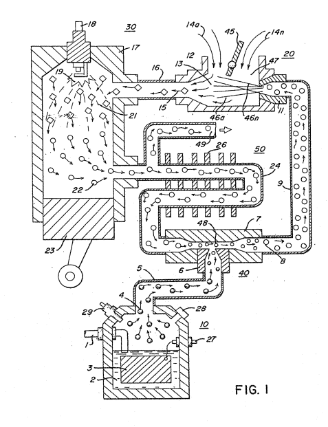
Figure 2 is a block schematic illustration of the preferred embodiment of Figure 1;
Figure 3 is an alternative gas system for that shown in Figure i;
Figure 4 is a block schematic illustration of a gas control system for retrofitting existing automobiles to a combustion system of the present invention; and
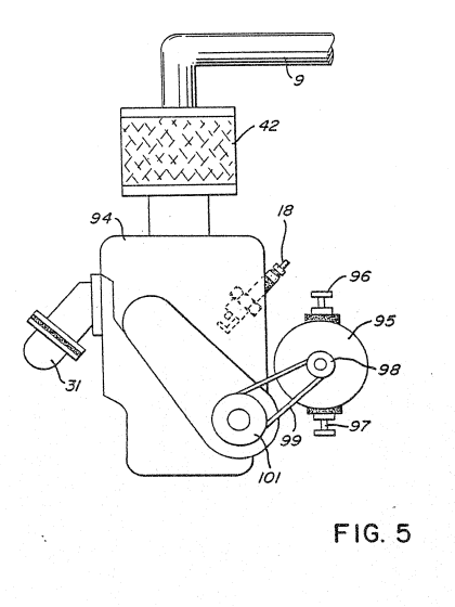
Figure 5 is a block schematic illustration of a regenerative energy feedback arrangement according to the present invention.
Description of Preferred Embodiments of the Invention
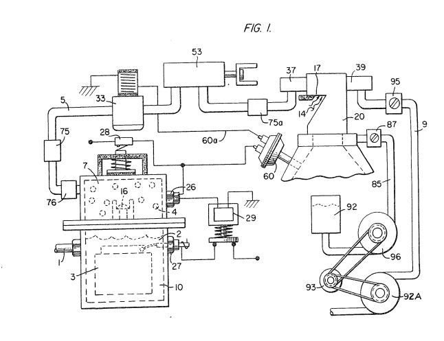
Referring particularly to Figure 1 the complete overall combustion system is illustrated together with a mechanical drive piston.
Similarly, Figure 2 illustrates the complete system in its preferred embodiment.
With particular reference to Figure 1, the hydrogen source 10 is the hydrogen generator disclosed and described in my aforementioned Application Serial No. 420,908 and includes an enclosure for a natural water bath 2. Immersed in the water 2 is an array of plates 3 of similar non-oxidizing material. Applied to plates 3 is a source of pulsed direct current potential via electrical inlet 27. The action of the pulsed direct current, a voltage/current potential, on the plates causes the hydrogen and oxygen atoms to become disassociated from the water molecule. In that the action is not a chemical action, any water irrespective of source may be utilized. Varying either the potential of the direct current source or the pulse rate of the pulsing of the direct current potential will vary proportionately the generation of the hydrogen/oxygen. Other factors are disclosed for varying the output of the generator. The water expended in the generator is replenished from continuous water source l. The hydrogen generator has a safety valve 28 which is rupturable upon excessive gas buildup, Switch 29 is a gas pressure switch to maintain a predetermined gas pressure level above a regulated low-volume.
The generated hydrogen gas 4 is Fed via pipe 5 to a gas mixing chamber 7, wherein the hydrogen gas is intermixed with non-combustible gases 22 from a source hereinafter described.
The mixture of combustible gas and non-combustible gases are fed via pipe line 9 to a carburetor (air-mixture) system 20.
The gas mixture 8 is fed through nozzle 11 to chamber 47 in a jet spray 46. Valve or gate 45 in the air intake controls the amount of air the jet spray 46 of gases combines with to form combustible mixture 15 which comprise hydrogen, non-combustible gases and oxygen. This mixture enters into combustion chamber 30, via pipe line 16. The chamber 30 may be conventional in design comprising a cylinder 17 capable of withstanding high pressure. At the uppermost end of combustion chamber 30 is a Spark plug igniter 18.
In a controlled manner, relative to the piston 23 stroke, the spark ignition 19 via plug 18 causes the mixed gases 15 to combust. The compression 21 caused by the combustion, forces the piston 23 to push downwardly in the cylinder 17.
The exhaust gases 22, the residue of the combustion 21, now comprise a non-combustible mixture.
A portion of these exhaust gases 22 are fed via pipe line 24 to the gas mixing chamber 40 providing the non-combustible gases for mixing with the generated hydrogen gas.
The pipe line 24 passes through cooling chamber 50 far cooling of the gases therein. The cooling chamber 50 also functions as a spark arrestor to eliminate the possibility of gas ignition inside the mixing chamber 40. The excess non-combustible gases are exhausted via outlet 49, to be expelled into the atmosphere.
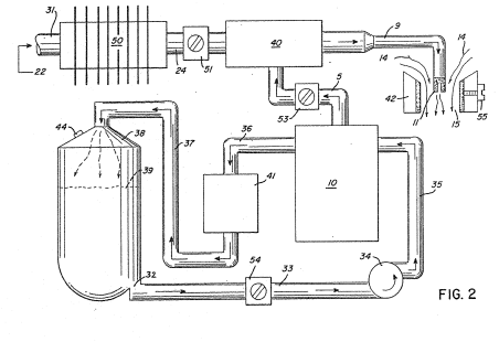
The apparatus of Figure 2 comprises much the same system as Figure 1. In this embodiment the components are depicted more explicitly in their structural relationship in an alternate arrangement. Basically, the system is operable in the same manner as that in Figure 1, i.e. it utilizes a mixture of combustible (hydrogen) gas and non-combustible gases (exhaust).
The hydrogen generator 10, as aforesaid, may be any form of a generator, however, in the preferred embodiment the hydrogen generator is that of my aforementioned co-pending patent application. The water system for the generator is a closed loop system comprising a reservoir oer tank 39 with piping to and from the generator. The reservoir has an outlet 32 connected to a pipe line 33 provided with a water control valve 54 operable to adjust the water Flow rate and a pump 34 connected by pipe line 35 to the generator 10.
The overflow water expended and non-expended is expelled from generator 10 into line 36, filtered in filter 41 to remove contaminants and returned to tank 39 via pipe line 37.
The gases generated from the water in generator 10 also includes the oxygen component of the water in addition to nitrogen.
The outlet 5 on the generator 10 receives the combustible (hydrogen)and non-combustible gases generated thereby and directs the same to the mixing chamber 40. The flow of the hydrogen gas is, of course, critical; therefore, there is incorporated in line 5 a gas Flow valve 53 to adjust the hydrogen gas flow.
The exhaust gases entering input 22 are fed via inlet pipe 31 through the cooling chamber also enter the mixing chamber and spark arrestor 50 and into outlet pipe 24. These gases from chamber 50 are flow controlled by flow control valve 51 in pipe line 24.
The output of mixing chamber 40, as described relative to Figure 1 is fed via line 9 to a gas mixture system 42. In this instance the intake air 14 may be in a carburetor arrangement with an intake adjustment 55 that adjusts the plate 42 opening. The gas mixture 15 is fad into the carburetor by nozzle 11 and mixed with the air 14.
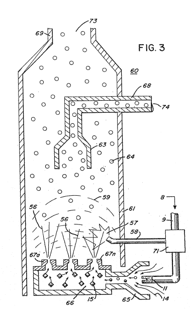
With particular reference to Figure 3 there is illustrated an alternative combustion chamber 60 that may be utilized in lieu of the chamber 30 of Figures 1 and 2.
In this embodiment the combustible and non-combustible gas mixture that is generated and mixed in the arrangement of Figures 1 and 2, enters inlet 8 and is directed by pipe line 9 and nozzle 11 to the cone 65. The gas mixture combines with air 14 as it enters the cone area 65 and the combined mixture combustible gas 15 is directed by the cone 65 to the dispersing chamber 66. The gas/air mixture 15 is dispersed via ports 67a xxx 67n from the dispersing chamber 66 into the firing area of the combustion chamber 60.
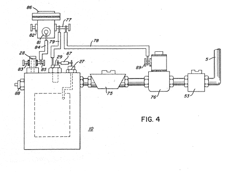
The gas mixture entering inlet 8 is also fed by pipe line 9 to a separation chamber 71. This chamber sections off a controlled amount of the intake gas mixture to a pilot light line 58. The pilot light firing gas 57 is also sequenced by the separation chamber 71 such as through an associated mechanical drive, much in the same manner as the cylinder of an automobile engine. The mixture designated gas 56, ejected from ports 67a xxx 67n of the dispersing chamber 66, is ignited by the pilot light and thereby causing combustion 59 of the mainstream gases, As the non-combustible gases 64 (exhaust gases 22 of Figure 1) rise upwardly in the cylinder 61, of the combustion chamber 60, the cone 63 captures a portion of the non-combustible gases 64. The captured exhaust gas is returned via pipe line 68 and outlet 74 to the combustion process as set in Figure 1 or expelled for other purposes. The major portion of the non-combustible gases 64 by-pass the cone 63 and rise further ta the outlet exhaust 69 and are expelled through opening 73. In Figure 4, there is illustrated a gas control system that may be retrofitted to an existing automobile internal combustion engine without changing or modifying its design parameters or characteristics. As low-voltage direct current is applied to safety valve 28, solenoid 86 is activated. ‘The solenoid applies a control voltage to the hydrogen generator plates 26 via terminal 27 through pressure switch 29. As the electrical power activates electric solenoid 86, hydrogen gas is caused to pass through flow adjustment valve 53 and then outlet pipe 5 for utilization.
Gas regulator valve 75 is utilized to reduce the pressure level inside the hydrogen generator 10. The pressure differential hydrogen gas output to gas mixing chamber 40 is, for example, 30 lbs. to 15 lbs. Once hydrogen generator 10 reaches an optimum gas pressure level, pressure switch 29 shuts off electrical power to the hydrogen exciters. If the chamber pressure exceeds a predetermined level, the safety release valve 28 is activated disconnecting the electrical current and thereby shutting down the entire system for safety inspection.
Similar to an automobile engine or other drive force requiring an electrical energizing source, the. present invention may include the regenerative energy feedback arrangement shown in Figure 5.
The process utilizes a mechanical drive system as described relative to Figures 1 and 2; and which mechanical drive may be that of a piston such as utilized in a gasoline engine. In operation, the process mixture is ignited much in the same manner as in Figure 1. ‘The drive mechanism in turn activates electrical voltage of alternator 95 whose output is fed back to the hydrogen generator and utilized as the firing voltage on the spark plug 18; again, in a closed loop arrangement.
|
|
Further, as aforesaid in my co-pending application, the Hydrogen Generator utilizes an electrical direct current voltage source on the energizer plates. In addition to the feedback closed loop as set forth with respect to the ignition system, the feedback system of Figure 6 is equally, and perhaps more significantly, applicable to the process of the hydrogen generator. That is, again referring to Figure 1, the electrical voltage applied to contact 27 is in the closed loop with the alternator/mechanical drive of Figure 5 In this way, the voltage requirements for the hydrogen generator are drastically reduced.
Depending upon the utility of the combustion chamber, the ratio of the combustible hydrogen gas and the non-combustible gas controls the combustion rate. Further, as understood oxygen is required for combustion, and it is present in ambient air that enters into the gas mixture line through the air intake. Again, the ambient air is understood to contain many and variable gases other than oxygen. Accordingly, air intake will add non-combustible gases to the gas mixture. This may require that the non-combustible gas intake be varied . . . and in some instances may not be necessary.
THE EMBODIMENTS OF THE INVENTION IN WHICH AN EXCLUSIVE PROPERTY OR PRIVILEGE IS CLAIMED ARE DEFINED AS FOLLOWS:
1. A combustion system comprising:
a hydrogen source;
a gas mixing chamber connected by suitable fluid flow passage means respectively to said hydrogen source and a further gas supply means via control valve means regulating the gas mixture ratio; and
means for mixing air with mixed gases from said mixing chamber and supplying the same to a gas burner wherein the gas/air mixture is ignited by suitable igniting means.
2. The combustion system of Claim 1 including valve means for controlling the amount of air mixed with said mixed gases.
3. The combustion system of Claim 1 wherein said means to ignite said gas/air mixture is a combustion chamber having an igniter.
4. The combustion system of Claim 3 further including a drive mechanism associated with said combustion chamber and wherein said drive mechanism is responsive to said air/gas burning in said combustion chamber.
5. The combustion system of Claim 3 wherein said combustion chamber further comprises outlet means for expelling the exhaust gases therefrom, and means for returning a portion of said exhaust gases to said mixing chamber,
6. The combustion system of Claim 4 wherein said hydrogen source is a hydrogen generator.
7. The combustion system of Claims 3, 4 or 5 wherein said hydrogen source comprises a hydrogen/oxygen generator which includes:
a housing having a water reservoir for retaining natural water therein and a gas collection chamber for maintaining a preset volume of gas under pressure;
and a pair of similar non-oxidizing plates, positioned in said water reservoir, adapted to be connected: to a direct current voltage source to disassociate the hydrogen atoms and oxygen atoms from said water molecules and thereby provide a gas.
8. The combustion system of Claim 1 wherein said hydrogen source is a hydrogen reservoir.
9. The combustion system of Claim 3, further including a pilot light ignition means and means for directing a portion of said gas/air mixture thereto.
10. a The combustion system of Claim 3 wherein said means to ignite said mixed gases comprises an electrical ignition means and a source of electrical energy.
11. The combustion system of Claim 3 wherein said combustion chamber comprises a mixed gas/air dispersing chamber having a series of ports therein.
12. The combustion system of Claim 4 wherein said drive mechanism comprises an internal combustion engine.
13. The combustion system of Claim 4 further comprising a source of electrical energy connected to said igniter in a closed loop mechanical arrangement with said drive mechanism.
14. The combustion system of Claim 5 wherein said means for returning a portion of said exhaust gases to said mixing means further includes cooling means for cooling said exhaust gases.
15. The combustion system of Claim 5 wherein said means for returning a portion of said exhaust gases to said mixing means further includes a spark arrestor for preventing uncontrolled combustion.
16. The combustion system of Claim 6 wherein said hydrogen generator includes a source of electrical potential, and wherein said source of electrical potential is connected in a closed loop mechanical arrangement with said drive mechanism.
17. A fuel supply and control system for a vehicle having a combustion engine that includes a combustion chamber and means for igniting the combustible fuel therein comprising:
(a) means for disassociating hydrogen atoms and oxygen atoms from water molecules to thereby provide a combustible gas;
(b) a gas mixing chamber;
(c) means directing a flow of said combustible gas and a portion of the products of combustion from said combustion chamber into said gas mixing chamber;
(d) means regulating the mixture ratio of said products of combustion and combustible gas to provide a first gas mixture;
(e) means for proportionately mixing said first gas mixture and air providing a second gas mixture; and
(f) means for controllably directing said second gas mixture into said combustion chamber for ignition therein by suitable igniting means.
18. A fuel supply and control system as defined in Claim 17 wherein said means for disassociating said hydrogen and oxygen atoms comprises a water reservoir with pairs of similar spaced apart non-oxidizing plates therein selectively connected to a direct current voltage source and a gas collection chamber.
19. A fuel supply and control system as defined in Claims 17 or 18 wherein said portion of exhaust gases pass through a cooler upstream of said gas mixing chamber.
20. A fuel supply and control system as defined in Claims 17 or 18 wherein said mixture regulating means comprises first and second control valves controlling respectively the flow of said combustible gas and said portion of the products of combustion to said gas mixing chamber.
21. A fuel supply and control system as defined in Claim 18 wherein water is controllably recirculated through said water reservoir.
PERLEY-ROBERTSON PANET, HILL & McDOUGALL PATENT AGENTS