
CA1234773A1 Resonant Cavity Hydrogen Generator That Operates with a Pulsed Voltage Electrical Potential
PDF Download: SMeyer-CA1234773A1-Resonant_Cavity_Hydrogen_Generator_That_Operates_with_a_Pulsed_Voltage_Electrical_Potential.pdf
Consumer and Consommation Corporate Affairs Canada al Corporations Canada
(11) (A) No. 1 234 773
(45) ISSUED 880405
(52) CLASS 204-78 C.R. CL. 158-14
(51) INT. CL. ¢C25B 1/04)
(54) Resonant Cavity Hydrogen Generator That Operates With a Pulsed Voltage Electrical Potential
(72) Meyer, Stanley A., U.S.A.
(21) APPLICATION No. 420 ,902
(22) FILED 830204
(30) PRIORITY DATE U.S.A. (P65,797) 820924 No. OF CLAIMS 22DISTRIBUTED BY THE PATENT OFFICE, OTTAWA. CCA-274 (11-82)
ABSTRACT
A process is disclosed for producing hydrogen and oxygen gasses from water which includes having water in a cavity which has a selected resonant frequency and applying of voltage potential to exciter elements in contact with the in the cavity so that one element maintains a positive charge and the other a negative charge. The voltage potential is pulsed at a frequency matching the resonant frequency of the cavity. The apparatus includes preferably a spherical shell which is a first exciter element formed of an electrically conductive non-reactive material and defines the boundary of a cavity. The cavity has a pre-determined resonant frequency and a second exciter element of the same material as the the first element is located within the cavity in selected spaced relationship therewith. Water can flow into the cavity gasses produced outflow from the top of the cavity, such gasses being obtained from the water in the cavity when an electrical pulsating potential is applied to the exciter elements
RESONANT CAVITY FOR A HYDROGEN GENERATOR CROSS REFERENCE:
In the non-electrolysis process disclosed and Claimed in my co-pending Canadain patent application, Serial Number 420,908, filed 4 February 1983, for HYDROGEN GENERATOR SYSTEM, for separating hydrogen and oxygen atoms from water, water is passed between two plates of similar non-oxidizing metal. The one plate has placed thereon a positive potential and the other a negative potential from a very low-direct— current power source. The action of the direct current voltage causes the hydrogen and oxygen atoms to be separated. The contaminants in the water also separated out and may be collected or utilized and disposed of. This in turn lends the process to recombining the hydrogen and oxygen into pure water.
The direct current voltage applied to the plates is non-regulated and non-filtered. The direct current acts as a static force on the water molecules whereas the rippling direct current voltage acts as a dynamic force. Pulsating the direct current further acts as a dynamic force and enhances considerably the splitting of the atoms from the water molecules. An increase in voltage potential further increases the hydrogen output. Certain plate arrangements and configurations with graphical illustrations of relative efficiency are disclosed.
In my co-pending patent application, supra, it was shown that the hydrogen gas generator is variably increased by varying the construction of the exciters; more particularly, by (1) increasing the area of the plates, (2) reducing the Space between the plates, and (3) altering the physical configuration of the plate.
SUMMARY OF THE INVENTION:
The basic structure of and principles of operation disclosed in the aforesaid co-pending patent application are utilized. The non-oxidizing exciters are of a construction, spherical in a preferred embodiment, with a given spacing between the positive and negative elements to form a resonant cavity at a given frequency. The direct current voltage is pulsed at a repetition rate (frequency) to match the resonant wavelength. At the matched frequency the action cof the 5 pulsed direct current voltage is enhanced considerably. The forceful action on the water molecule causes the molecules to break into their atomic structure at a much more rapid rate;
thereafter, the gas atoms are set into motion within the resonant cavity, thereby increasing velocity to a jet-like action as they are released from a port.
The single resonant cavity has a controlled size port for the utilization of the high velocity gasses.
The resonant cavity plate structure in a preferred arrangement is an array of elements. The gasses emitted from the array are combined and expelled as high velocity gasses from a common nozzle and utilized.
A principal object of the present invention is to provide an improved method and apparatus for the separation of hydrogen/oxygen gasses from water.
In accordance with one aspect of the present invention there is provided a process for producing a gaseous medium which includes hydrogen and oxygen from water, comprising: providing at least one pair of spaced apart electrically conductive , non-oxidizing exciter elements in association with a cavity having a selected resonant frequency and in which there is water, said exciter elements being in 4 contact with the water in the cavity, applying a voltage potential to said exciter elements such that one element maintains a positive charge and the other a negative charge, 30. and pulsing the voltage patential at a frequency matching the resonant. frequency of the cavity. In accordance with a further aspect of the present invention there is provided apparatus for producing a gaseous, medium which includes hydrogen and oxygen from water 35 comprising a first exciter element formed of an electrically conductive non-reactive material having a surface which defines the boundaries of a cavity, said cavity having a predetermined resonant frequency with a quantity of water therein, a second exciter element of the said same material within said cavity in selected spaced relationship from said first exciter element, means permitting the inflow of water into said cavity and means permitting the outflow of gasses from said cavity, said gasses being obtained from water in the cavity when an electrical pulsating potential is applied to said exciter elements.
BRIEF DESCRIPTION OF DRAWINGS:
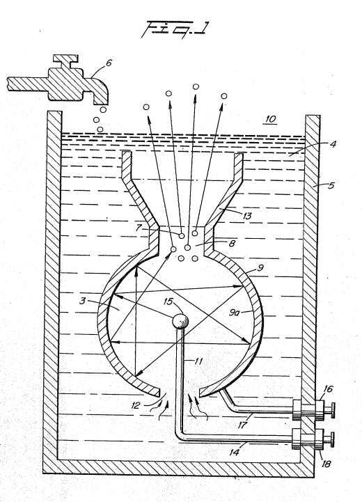
Figure 1 is a schematic illustration of the structure of the present invention in its most simplified arrangement.
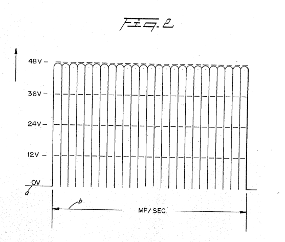
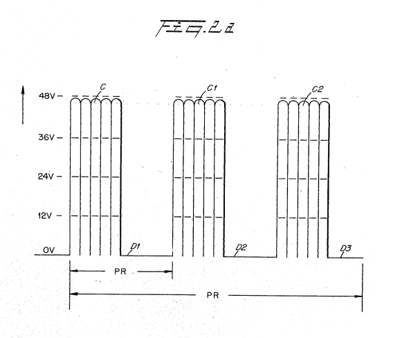
Figures 2, 2A, and 2B, are a series of waveforms illustrating the pulse rate of the direct current to’ match the resonant frequency of the structure of Figure 1.
 |
 |
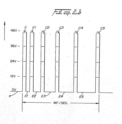 |
Figure 3 is a schematic illustration of the utilization of the structure of Figure 1.
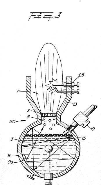
Figure 4 is a first alternative structure to that shown in Figure 1.
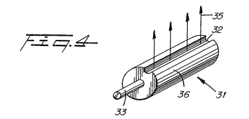
Figure 5 is another alternative structure to that shown in Figure 1.
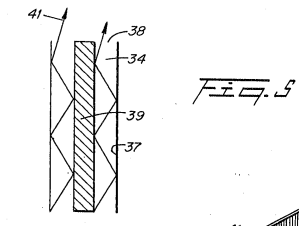
Figure 6 is another alternative structure to that shown in Figure 1.
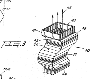
Figure 7 and 7A are an array of exciters, such as shown in Figure 1, in a preferred embodiment.
 |
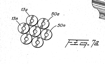 |
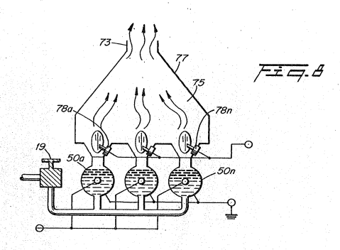
Figure 8 is an array of exciters, such as shown in Figure 3, in a preferred embodiment.
DETAILED DESCRIPTION OF INVENTION:
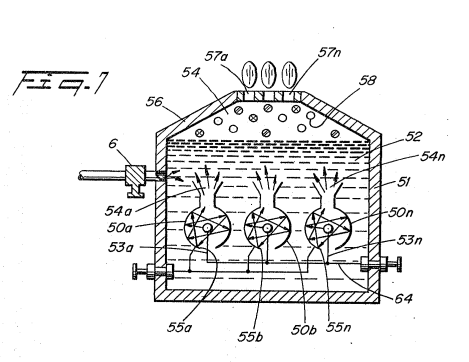
Reference is now made to the several figures depicting the preferred embodiment of the present invention. Referring to Fig. 1. there is illustrated a device 10 which includes a vessel 5 having therein an outer shell 9 and an inner element 15. The shell 9 has a gas expulsion opening 8 in its uppermost region, and a gas guide 13 flared out from the opening 8.
Shell 9 and element 15 are spherical the latter being centrally positioned within the sphere 9 and of much smaller diameter. The outer shell 39 is the grounded negative side and adopted to and connected to a suitable DC voltage source via terminal 16 and wire 17. The inner element 15, is adapted for connection to the positive side of the potential via terminal 18, wire 14 and a support 11 for the element 15 which enters shell 9 through a water intake opening 12 in the lower end thereof.
The vessel 5 contains water 4, replenished from a source through faucet 6, at a level above the shell 9 and element 15. The water 4 flows into the cavity of shell 9 through the lower opening 12,
As described in my aforesaid patent application the direct current electrical potential is in the nature of a physical force on the water molecule which causes the water molecule to break up into its atomic structure liberating hydrogen and oxygen in gaseous form from the water. Also other gasses, such as nitrogen, that may be entrapped therein will be released.
In that the aforesaid process is not an electrolysis process, water of any origin may be used, irrespective of the contaminant content. In the process, as the gasses are released the contaminants will be separated and fall to the bottom of the container.
Again, since the process does not in fact generate hydrogen but simply releases the hydrogen, the process is most efficient and not power intensive. The direct current voltage/potential is of extremely low voltage and only of an insignificant current.
There is described in the process of my co-pending patent application apparatus and methods for increasing the output of hydrogen for a given voltage/potential input. For instance plate spacing and plate area are discussed; pulsing the direct current and applying an unfiltered direct current all in one manner or another enhances the release of hydrogen, Increasing the voltage/potential will increase the gas output proportionally.
In each of the apparatus or methods for increasing the output, the physical force applied to the water molecule is the controlling factor. It can be appreciated that limitations may be reached in the control of these dynamic and static forces.
in the present invention, the preferred embodiment utilizes in one manner or another, all of the aforementioned output control factors and is directed primarily to pulsing the direct current potential.
It has been found that the distance between plates of the exciters will have, or can be adjusted to have, a ‘wavelength or partial wavelength, or a multiple wavelength, related to the motion of the water molecule in travelling from the one plate to the other. Therefore, the structure is constructed to be a resonant cavity at some given frequency of the molecular motion.
With specific reference again to Figure 1, the distance from the outer surface of the central element 15 to the inner surface 9a of the outer spherical element 9 will be at some wavelength correlated to the molecular motion of travel. When the wavelength is matched with a physical force equal in frequency to that wavelength the inner area becomes a resonant cavity. As understood in resonant cavities of an electron nature, the molecules are set into motion and will be bombarded back and forth from the one surface to the next continuously so long as the initial force is applied.
In the sphere of Figure 1, the directions that the water molecules may travel from the inner sphere 15 to the surface 9a of the other sphere 9 is of an infinite number. Considering a single molecule, the water molecule's motion will under normal conditions be impeded by the water. If the distance between the inner and outer sphere is co-related to a wavelength related to the frequency of the pulsating direct current applied to the water, the water molecule will be set in motion and thereafter enhanced in motion in the resonant cavity 3 and overcome the impediment of water.
Further, the molecule upon striking the inside surface of the outer sphere, will be reflected and directed to an angular surface where it again will be reflected. This action continues indefinitely and will continue until the applied energy is terminated. Thus, a resonant cavity causes the water molecule to travel back and forth continuously and at a velocity that increases geometrically.
The above-noted single molecule's motion of travel will be further increased in velocity when it is considered that the number of water molecules is infinite and the striking force is not only from surface-to-surface but also from molecule-to-molecule.
The enhanced physical action on the water molecule in the resonant cavity 3 will directly affect the breaking up of the molecule into its gaseous atomic structure. As this occurs, the hydrogen, oxygen and other gasses that may be released from the water will be similarly set into motion. The gas atoms will be reflected from the surface 9a and bombard each other in geometric proportion to the energy applied. The water impediment now is relatively insignificant.
 With reference to the graph of Figure 2, the direct current input voltage a is pulsed at a repetition rate, as shown by waveform 6, (per second) equal to the resonance frequency of the cavity 3.
To enhance the forceful action of the applied pulsed direct current voltage/potential on the water molecule and the sub-atomic action for the release of gasses, the pulsing of the direct current is periodically interrupted as shown in the graph of Figure 2A. That is, the pulse frequency and pulsed direct current C, C1, and C2 is interrupted in uniform intervals d1, d2, and d3.
Again, the pulsed direct current may be periodically interrupted, That is, the interruption between pulses C, C1, C2, and C3... is for different time periods: e, e1, e2, and e3.
Returning to Figure 1, an opening @ is provided in the uppermost portion of the outer sphere 9 of the resonant cavity 3 structure. The travel of the gas atoms 7 bombarding back and forth in the resonant cavity 3 will eventually pass through the opening 8. However, the movement of the gas atoms 7 has been accelerated as aforesaid and when they pass through the opening 8 they are at an extremely high velocity. That is, the motion of the gas atoms 7 will pass out of opening 8 as though they are jet propelled.
The structure of Figure 1 is that of a sphere 9 with another sphere 15 positioned therein. The spacing between the outer surface of the inner sphere 15 to the inner wall 9a of sphere 9 provides a resonant cavity to a given frequency of the physical force of the direct current voltage. Other resonant cavities may be utilized in other arrangements.
In Figure 3 the resonant cavity structure 20 is utilized in a first completed self contained embodiment. Water 4 enters via nozzle 19 directly into the chamber of the closed sphere 9.
The structure of Figure 3 is substantially identical in operation to that of Figure 1. However, in this embodiment, the opening 8 has a nozzle 2 therein with ports of selected size. The velocity of the gasses being expelled determines the sizes of the ports of the nozzle 2. ‘That is, the ports in the nozzle 2 must be sufficiently large to permit an adequate amount of gas to be expelled to maintain a flame, but not so small that the velocity of the gasses expelled would be so great that combustion cannot be sustained. The direction of the high velocity gasses is controlled by guide 13. The gasses 7. may be ignited by igniter 25 or utilized directly in another manner.
The resonant cavities of Figures 1, 3, and 7 are related to the spacing between an outside and an inside spherical structure comprising a resonant cavity to the excited atoms .in the atomic process. Other configurations particularly those shown in the aforesaid co-pending patent application, may be constructed or modified to be resonant cavities. The resonant cavities will enhance the release of the gasses, irrespective of their configuration. However, the structure that is found most productive may be related to its utilization in an operable embodiment.
|
|
More particularly, the resonant cavity of Figure 4 is an elongated exciter 31. The Spacing between the elements 33 and 36 provide the resonant cavity. The gasses 35 in this embodiment will be jettisoned broadside along the slot 32.
In Figure 5 there is illustrated the coaxial exciter arrangement of the preferred embodiment of the aforementioned co-pending patent application. In this embodiment the spacing 34 between the inner plate 39 and the inner wall of the outer element 37 is adjusted to be resonant at a given frequency. The input direct current is pulsed accordingly. The gasses are propelled along the longitudinal axis of the elements 37 and 39 and expelled from the end 38 of the exciter.
Corrugations
The exciter 40 of Figure 6 is an improvement over an earlier development in that increased surface area is provided by corrugations in the walls that create the resonant cavity.
The corrugations provide an enhancement of the sub-atomic action on the water entering at 44. The spacing 46 between the plate 41 and plate 42 is such that the cavity is resonant at a particular frequency, as aforementioned.
However, instead of a forward direct line back-and-forth path of the atom flow, the corrugations of the convex 47 and concave 49 surfaces cause the atoms to move in a forward and backward of back~and-forth path.
The increased movement, in turn, increases the sub-atomic action and the velocity of the flow of gasses 45 emitted from the end 43 of exciter 40.
Referring now to Figures 7 and 7A, the structure of Figure 1 is in an array of resonant cavities 50a to 50n. Specifically, the housing 51 having water 52 therein includes the array of exciters, having a positive potential applied to its central element 53a to 53n, via terminal 64 and a negative potential to the outer element 55a to 55n.
|
|
The direct current potential is pulsed in a repetitive frequency, as noted above, to match the frequency of the resonant cavity. The gasses 54a to 54n being released from respective ones of exciters 50a to 50n are directed by the guide walls 56 to the upper chamber 58 wherein the high velocity gasses 54 are accumulated. As the gasses 54 are accumulated the pressure in the upper chamber 58 increases proportionally.
With reference to Figure 3, the port 2 is correlated in size of opening relative to the velocity of the gasses. If the port 2 is oversize the velocity of the gasses will be so great that a flame could not be sustained and backfire may occur, hence the port size is limited.
In Figure 7, the ports 57a to 57n may be greater in size that the individual port 2 of Figure 3. The individual outputs are not utilized to support a flame hence the significance of limiting the port size and the danger of flashback is not critical. The outputs from each of the exciters are accumulated as gasses 54 in a master chamber 58.
With particular reference now to Figure 8 there is illustrated an array of the gas exciters illustrated in Figure 3. The operation of the individual gas exciters is identical to that of Figure 3 except that in the array the several gas flames from the individual exciters are accumulated in chamber 75.
 |
|
Throughout the above specification the term "plate" is used to denote an element as described. It is specifically understood that the term plate is not to be limited to a flat or planar construction, but may be a structure of any configuration.
Although certain embodiments are shown, modification may be had without departing from the spirit and scope of the invention.
In the foregoing there is described with reference to the drawings, apparatus for obtaining a gaseous medium which includes hydrogen and oxygen from water.
The following is a brief explanation as to what is believed takes place in practicing the invention.
A water molecule is exposed to a potential difference physically between one positively charged and one negatively charged electrical voltage zone. The unlike hydrogen and oxygen atoms, already having a positive negative charge in the bound molecule, assume opposing electrical characteristics that are equal. in magnitude and potential. In the zone of potential difference the electrical polarity of the water molecule is stabilized. Although the molecule is stabilized in electrical polarity by the application of the potential difference, the bond between the atoms becomes weakened.
The electrical polarization of the water molecule according to the invention is basically a four step process: First, the water molecule is subjected to a potential difference physically in oppositely charged electrical voltage zones. Second, the water molecule becomes electrically polarized. Third, the electrical polarization of the molecule as it affects the electrical charges of the component hydrogen and oxygen atoms greatly weakens the stability of the overall molecule. And fourth, because the voltage zones are present and have opposite electrical attractions, the electron bonding of the hydrogen and oxygen atoms molecule is broken and the molecule splits into its component atoms. The hydrogen is attracted to the negative electrical voltage zone, while, simultaneously, the oxygen is attracted to the positive electrical voltage zone.
Because the bond between the hydrogen and oxygen is already weakened by the first electrical polarization of the water molecule, little energy in the form of applied voltage is needed to actually separate the hydrogen and oxygen atoms. Voltage, a potential energy and not energy consumption (amps), provides the threshold impetus for the atoms to break away from one another in ‘the molecule ina strictly physical process. Hydrogen gas and oxygen gas are released in great amounts with little energy consumed, and without chemical interactions. Once the molecule splits, the liberated hydrogen and oxygen atoms will not recombine.
In an explanation of the theory of operation of the invention a water molecule (H20) in a normal state has a molecular bond in a neutral molecule that includes the sharing of electrons between two nominally positive hydrogen atoms and a nominally negative oxygen atom. The molecule itself is in a neutral, uncharged, stable state.
In the invention, electrical voltage zones are created. The atoms of the normally neutral water molecule take on an electrical charge; the oxygen atom takes on a negative electrical charge; the hydrogen atoms take on a positive charge. The covalent electron bonding of the molecule is disrupted by the introduced electrical charge and is weakened. Separation of the atoms, and the production of gas, occurs between the plates. The process is preferably done in a non-chemical environment; thus, any form of "natural" water may be utilized without additives or chemicals. Voltage zones are provided by electrically conductive non-oxidizing, non-corrosive, non-reactive excitor plates (formed from a material such as stainless steel) placed in a non-chemical, non-reactive housing. A voltage is applied to the excitor plates to provide a potential energy.
Although current leakage will occur because of the residual conductivity of the water in the invention the flow of amperes is limited deliberately in any well known manner so as to be insignificant.
Contaminants present in water do not affect the process.
Gas production is achieved by pulsing the potential difference that creates the electrical voltage zones in a variable, repetitive manner. In general, the production of gas increases with either or both of the voltage applied and/or the frequency of: the voltage pulse.
Because of the ability to control the gas production rate the method and apparatus of the invention provides a fuel cell that is a constant energy source.
In practical application, there is no need for secondary storage medium for the gas produced. Natural water is the safest medium in which to store hydrogen atoms until they are needed for consumption. If the fuel cell is ruptured, the only material to spill out would be harmless water.
THE EMBODIMENTS OF THE INVENTION IN WHICH AN EXCLUSIVE PROPERTY OR PRIVILEGE IS CLAIMED ARE DEFINED AS FOLLOWS:
1. A process for producing a gaseous medium which includes hydrogen and oxygen from water, comprising:
providing at least one pair of spaced apart electrically conductive, non-ox <idizing exciter elements in association with a cavity having a selected resonant frequency and in which there is water, said exciter elements being in ‘contact with the water in the cavity;
applying a voltage potential to said exciter elements such that one element maintains a positive charge and the other a negative charge, and pulsing the voltage potential at a frequency matching the resonant frequency of the cavity.
2. A process as set forth in claim 1 wherein one of said pair of exciter elements is a shell providing said cavity.
3. A process as defined in claim 2 wherein said shell is a first sphere and wherein said other element is a second sphere, said second sphere being substantially smaller in size than said shell.
4. A process as defined in claim 3 wherein said spherical shell includes a first and second spaced apart opening providing respectively a water inlet into the cavity and an outlet for the gases.
5. A process as set forth in claim 1 including a plurality of pairs of exciter elements arranged in an array of ‘identical pairs.
6. A process as set forth in claim 5 wherein the gases from the array of exciter elements are collected in a common chamber.
7. A process as defined in claim 1 wherein said applied potential produces a gaseous medium in the cavity an including the step of regulating the output of the gaseous medium from said cavity.
8, A process for obtaining a gaseous medium which includes hydrogen and oxygen from water comprising
(a) providing a pair of electrically conductive non-oxidizing exciter elements in selected Spaced apart relation and arranged such as to provide a cavity therebetween which has a predetermined resonant frequency;
{b) placing water in said-cavity;
{c) applying an electrical voltage potential across said elements and pulsating the Same, without any change of polarity, at a frequency corresponding to said resonant frequency of the cavity; and
(d) collecting the gases separated from the water in said cavity resulting from said applied pulsed voltage potential.
9. Apparatus for producing a gaseous medium which includes hydrogen and oxygen from water comprising a first exciter element formed of an electrically conductive non-reactive material having a surface which defines the boundaries of a cavity, said cavity having a predetermined resonant frequency with a quantity of water therein, a second exciter element of the said same material within said cavity in selected spaced relationship from said first exciter element, means permitting the inflow of water into said cavity and means permitting the outflow of gases from said cavity, said gases being obtained from water in the cavity when an electrical pulsating potential is applied to said exciter elements.
10. A process as set forth in claim 1 wherein the pair of exciter elements are coaxial and radially spaced providing therebetween said cavity and wherein the outermost element has an opening for the escape of gas from the cavity.
11. An apparatus as set forth in claim 9 wherein said exciter elements are in a coaxial radial spaced relations, the space therebetween being said resonant cavity.
12. An apparatus as defined in claim 11 wherein said coaxial arrangement is such that the cavity is closed at one end and open at the other opposite end.
13. An apparatus as set forth in claim 9 further including igniter means for igniting the gases that outflow from said cavity.
14. An apparatus as set forth in claim 9 including a plurality of said pairs of said exciter elements disposed side-by-side in an array.
15. An apparatus as set forth in claim 14 including means to accumulate the gases output from the respective pairs of exciter elements in a common chamber.
16. An apparatus as defined in claim 9 including a nozzle regulating the outflow of gases from said cavity.
17. An apparatus as defined in claim 9 wherein said first exciter element is a spherical shell.
18. An apparatus as defined in claim 17 wherein said second exciter element is spherical,
19. An apparatus as defined in claim 18 wherein said spheres are concentric and radially spaced, the space between said spheres providing said cavity.
20. An apparatus for producing a mixture of gases derived from water comprising a closed vessel suitable for maintaining a volume of water therein and permitting the addition of water thereto as the water therein is being depleted, means for providing an electrical potential difference within said vessel comprising a pair of electrically conductive exciter elements formed of the same non-reactive material positioned to be in the water in said vessel in a predetermined spatial relationship to one another to define a resonant cavity at a predetermined wavelength; a source of pulsating voltage potential that creates a potential difference between an arbitrary electrical ground and the source output in a waveform correlated to the predetermined resonance wavelength of the cavity; means for connecting one of said exciter elements to said arbitrary electrical ground and the other of said exciter elements to said source output, whereby there is formed during use of the apparatus a nominally positive electrical voltage zone in water adjacent the exciter element connected to said output and a’ nominally negative voltage zone in water adjacent the exciter element connected to said electrical ground as the pulsating voltage potential having the predetermined wavelength is applied thereto, the pulsating voltage potential during operation of said apparatus being applied to said exciter elements to a sufficient magnitude as to cause the electrical polarization of the water molecules in the vicinity thereof and to thereafter cause the hydrogen atoms of the water molecule to be attracted to said negative zone, and the oxygen atoms to be attracted to said positive zone, and thereby to create a resonance within the. cavity and weaken the bond between the hydrogen atoms and the oxygen atom so that said atoms disassociate from the water molecule and are released in the form of a gas mixture; and means for collecting and dispensing said mixture of gases.
21. An apparatus as set forth in claims 3 or 20 including means to repetitively pulse direct current voltage potential across said exciter elements while maintaining a positive charge on one and a negative charge on the other and means to periodically interrupt said pulsing.
22, Apparatus as set forth in claims 9 or 20 wherein elements are non-oxidizing.