
CA1233379A1 Hydrogen Gas Injection for Internal Combustion Engine
PDF Download: SMeyer-CA1233379A1-Hydrogen_Gas_Injection_for_Internal_Combustion_Engine.pdf
Consumer and Consummation Corporate Affairs Canada et Corporations Canace
(a) (A) No. 1 233 379
(45) ISSUED 880301
(52) CLASS 123-15 C.R. CL. 60-14
(51) INT. CL. FO2M 21/04as) can CANADIAN PATENT «2
(54) Hydrogen Gas Injector for Internal Combustion Engine
(72) Meyer, Stanley A., U.S.A.
(21) APPLICATION No. 420,910
(22) FILED B30204
(30) PRIORITY DATE U.S.A. (349,185) 820217 No. OF CLAIMS 18Canada
DISTRIBUTED BY THE PATENT OFFICE, OTTAWA. CCA-27-4 (11-82)
ABSTRACT
A system and apparatus for the controlled intermixing of hydrogen gas with oxygen and other non-combustible gases in a combustion system is disclosed and can be used, for example, in an internal combustion engine. In the system, there is provided a hydrogen/oxygen generator, a water reservoir including a gas collection chamber, non-oxidizing plates in the reservoir and a direct current source connected to the plates for disassociation of hydrogen and oxygen atoms. The hydrogen gas is directed to a mixing chamber employing a fuel linear control valve. Non-combustible gas is also introduced into the mixing chamber and there is also ambient air intake means for combining air with the hydrogen gas and non-combustible gases. Controlled amounts of hydrogen gas combined with the non-combustible gas and ambient air are fed to the combustion chamber of the internal combustion engine.
CROSS REFERENCES AND BACKGROUND
There is disclosed in my co-pending Canadian Patent Application Serial No 420,908, filed February 4, 1983 for a Hydrogen-Generator, a generating system converting water into hydrogen and oxygen gases. In that system and method the atoms are dissociated from a water molecule by the application of a non-regulated, non-filtered, low-power, direct current voltage electrical potential applied to two non-oxidizing similar metal plates having water passing therebetween. The action is enhanced by pulsing the non-regulated and non-filtered direct current voltage. The apparatus comprises structional configurations in alternative embodiments for segregating the generated hydrogen gas from the oxygen gas.
I have also devised a way whereby, non-combustible gases can be controlled in a mixing stage with a combustible gas. This hydrogen processor system utilizes a rotational mechanical gas displacement system to transfer, meter, mix, and pressurize the various gases. In the gas transformation process, ambient air is passed through an open flame gas-burner system to eliminate gases and other present substances. Thereafter the non-combustible gas-mixture is cooled, filtered for impurity removal, and mechanically mixed with a predetermined amount of hydrogen gas. The gas formation stage also volume meters and determines the proper gas-mixing ratio for establishing the desired burn-rate of hydrogen gas. The rotational mechanical gas displacement system in that process determines the volume-amount of gas to be produced.
The above-noted hydrogen processor is a multi-stage system having a utility in special applications. Whereas the hydrogen generator system of my other mentioned co-pending application does disclose a very simple and unique hydrogen generator.
I have also developed a combustion system having utility in a mechanical drive system. Particularly in one instance to drive a piston in’ an automotive device.
It involves a hydrogen generator for producing hydrogen gas from water. The hydrogen gas with the attendant non-combustible gases are fed via a line to a controlled air intake system. The combined hydrogen, non-combustible gases, and the air after inter-mixing are fed to a combustion chamber where it is ignited. The exhaust gases of the combustion chamber are returned in a closed loop arrangement to the mixing chamber for the mixture of combustible and non-combustible gases.
SUMMARY OF INVENTION
The system of the present invention in its most preferred embodiment is for a combustion system utilizing hydrogen gas; particularly to drive a piston in an automobile device. The system utilizes a hydrogen generator for developing hydrogen gas. The hydrogen gas and other non-combustible gases are fed to a mixing chamber also having oxygen fed thereto. The mixture is controlled to regulate the burning temperature; that is, to lower the temperature velocity of the hydrogen gas to that of the commercial fuels. The hydrogen gas feed line to the combustion chamber includes a fine linear control gas flow valve. An air intake is the source of oxygen and it also includes a variable valve. The exhaust gasses from the combustion chamber are utilized in a controlled manner as the non-combustible gasses.
The hydrogen generator is improved upon to include a holding tank to provide a source of start-up fuel. Also, the hydrogen gas generator includes switch to the power source operable from one position to another dependent upon a pressure sensing switch on the combustion chamber.
The simplified structure includes a series of one-way valves, safety valves, and quenching apparatus. The combination of apparatus comprises the complete assembly for converting the standard automobile engine from gasoline (or other fuels) to the hydrogen gas mixture.
OBJECTS
It is, accordingly, a principal object of the present invention to provide a combustion system of gasses combined from a source of hydrogen and non-combustible gasses. Another object of the invention is to provide such a combustion system that intermixes the hydrogen and non-combustible gasses in a controlled manner and thereby control the combustion temperature.
A further object of the invention is to provide such a combustion system that controls the Fuel flow to the combustion chamber in a system and apparatus particularly adapted to hydrogen gas.
Still other objects and features of the present invention will become apparent from the following detailed description when taken into conjunction with the drawings in which:
BRIEF DESCRIPTION OF THE DRAWINGS
Figure 1 is a mechanical schematic illustration partly in block form of the present invention in its most preferred embodiment.
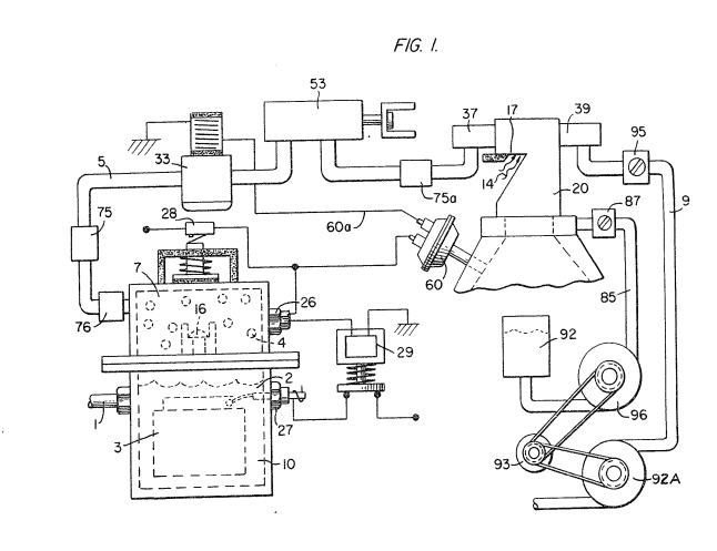
Figure 2 is a block schematic illustration of the preferred embodiment of the hydrogen injector system of Figure l.
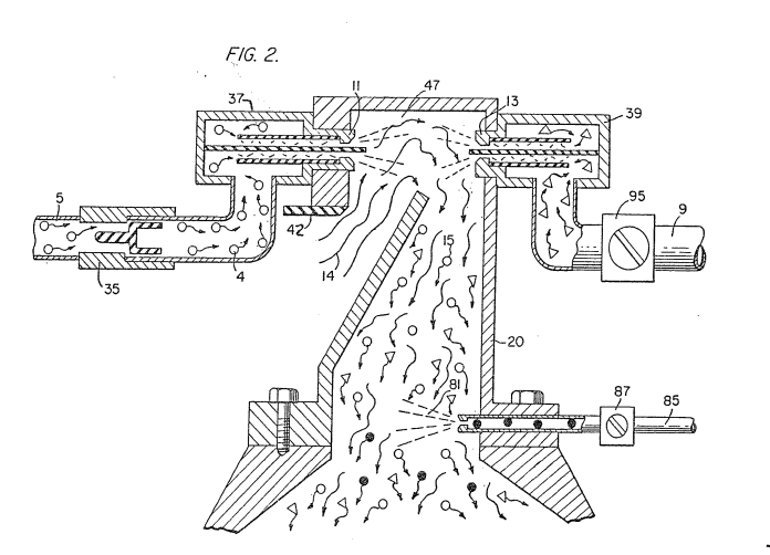
Figure 3 is the fine linear fuel flow control shown in Figure l.
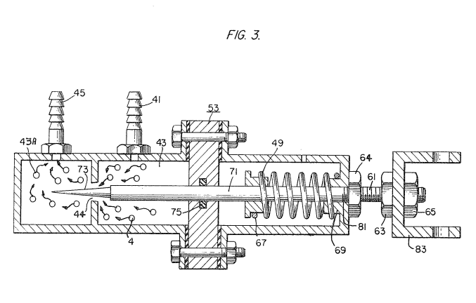
Figure 4 is cross-sectional illustration of the complete fuel injector system in an automobile utilizing the concepts of the present invention.
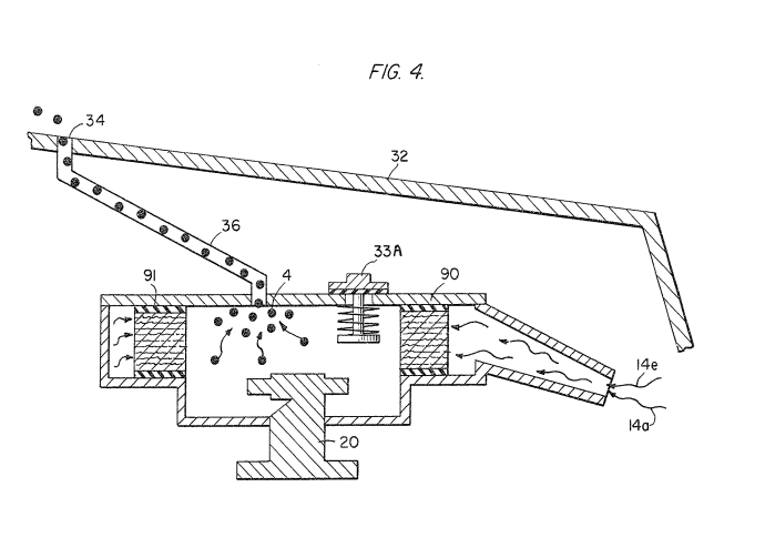
Figure 5 is a schematic drawing in a top view of the fuel injector system utilized in the preferred embodiment
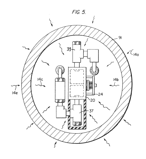
Figure 6 is a cross-sectional side view of the fuel injector system in the present invention.
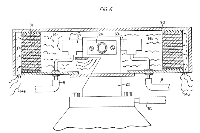
Figure 7 is a side view of the fuel mixing chamber.
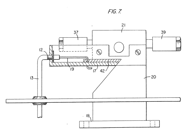
Figure 8 is a top view of the air intake valve to fuel mixing chamber.
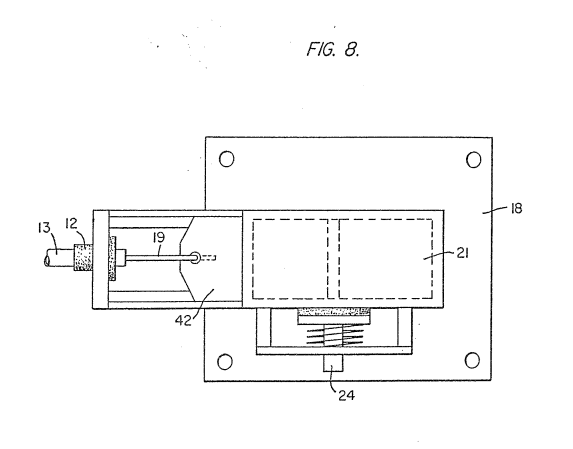
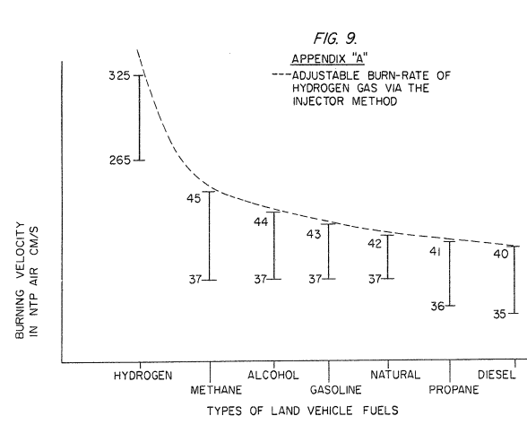
Figure 9 is a graphical illustration of the adjustable burn-rate of hydrogen gas.
DETAILED DESCRIPTION OF INVENTION TAKEN WITH DRAWINGS
Referring to Figure 1, the complete overall gas mixing and fuel flow system is illustrated together for utilization in a combustion engine particularly an engine utilized in an automobile.
With specific reference to Figure 1, the hydrogen source 10 is the hydrogen generator disclosed and described in my co-pending application, supra and includes a container which is an enclosure for a water bath 2 (natural water). Immersed in the water 2 is an array of plates 3 as further described in my co-pending application, supra and selectively applied (note solenoid 29) to plates 3 is a source of direct current potential via electrical inlet 27. The upper portion 7 of the container is a hydrogen storage area maintaining a predetermined amount of pressure. In this way for start up there will be an immediate flow of hydrogen gas. To replenish the expended water in the generator there is provided a continuous water source 1. Thereafter, the generator is operable as described in the aforesaid patent application.
The safety valve 28 is rupture-able upon excessive gas build-up and switch 26 is a gas pressure switch to maintain a predetermined gas pressure level.
The generated hydrogen gas 4 is fed from the one-way check valve 16 via pipe 5 to a gas mixing chamber 20, wherein the hydrogen gas is inter-mixed with non-combustible gasses that enter via pipe line 9 from a source hereinafter described.
In the event one way valve 75 should fail and there be a return spark that might ignite the hydrogen gas 4 in the storage area 7 of hydrogen generator 10, quenching assembly 76 will quench the spark and prevent such ignition. With particular reference to Figure 2 the hydrogen gas via pipe line 5 and non-combustible gasses via pipe line 9 are fed to a carburetor (air-mixture) system 20 also having an ambient air intake 14. The hydrogen gas 4 is fed via line 5 through nozzle 11 in a spray into the trap area 47 of the mixing chamber 20. Nozzle 11 has an opening smaller than the
plate openings in the quenching assembly 37, thereby preventing flash back in the event of sparking. The non-combustable gasses are injected into mixing chamber 20 trap area in a jet spray via nozzle 13. Quenching assembly 39 is operable much in the same manner as quenching assembly 37.
The ambient air is, in the preferred arrangement, the source of oxygen necessary for the combustion of the hydrogen gas. Further, as disclosed in the aforesaid co-pending application the non-combustible gasses are in fact the exhaust gasses in a closed loop system. It is to be understood that the oxygen and/or the non-combustible gasses can be from an independent source.
With continued reference to Figure 2 the gas trap area 47 is a predetermined size. In that hydrogen is lighter than air, the hydrogen will rise and become entrapped in the area 47. The size of area 47 is sufficient to contain enough hydrogen gas for instant ignition upon start up of the combustion engine.
It will be noted that the hydrogen gas is injected in the uppermost region of the trap area 47. Hydrogen rises at a much greater velocity than oxygen or non-combustible gasses; perhaps three times or greater. Therefore, if the hydrogen gas entered the trap area 47 (mixing areas) at its lowermost region the hydrogen gas would rise so rapidly that the air could not mix with the oxygen. With the structure shown in Figure 2 of the trap area 47, the hydrogen gas is forced downwardly into the intake air. That is, the hydrogen gas is forced downwardly into the upwardly flowing air and readily mixed therewith.
The ratio of the ambient air (oxygen) and the non-combustible gas via line 9 is a controlled ratio and determined by the particular engine. Once the proper combustion rate is determined by the adjustment of valve 95 for varying the amount of the non-combustible gas and the adjustment of valve iS for varying the amount of the ambient air, the ratio is maintained.
In a system wherein the non-combustible gasses are the exhaust gasses of the engine in a closed loop arrangement and wherein the air intake is under the control of the engine, the flow velocity and hence the air/non-combustible mixture, is maintained by the acceleration of the engine.
The mixture of air with non-combustible gasses becomes the carrier for the hydrogen gas. That is, the hydrogen gas is superimposed on the air/non-combustible mixture. By varying the amount of hydrogen gas superimposed 10 on the air/non-combustible mixture, the r.p.m. of the engine is controlled.
Reference is made to Figure 3 illustrating precisely in a side view cross-section the fine linear fuel flow control 53. The hydrogen gas 4 enters chamber 45 via gas inlet 41. The hydrogen gas passes from chamber 43 via port or opening 44. The amount of gas passing from chamber 43 to chamber 43A is controlled by controlling the port opening 44.
The port opening is controlled by the insertion there through the linearly tapered pin 73. The blunt end of pin 73 is fixed to rod 71. Rod 71 passes through a supporting O-ring 75 and through an opening 81 in a housing to manual adjustment mechanism 83.
The spring 49 retains the rod 71 in a fixed position relative to the pin 73 and opening 42. Upon actuating the mechanism 83, the pin 73 will recede from the opening 44 thereby increasing the amount of gas passing from chamber 43 to chamber 43A.
The stops 67 and 69 maintain spring 49 in its stable position. The position of the pin 73 in a fixed position relative to opening 44 is adjusted via threaded nut 64 on threaded rod 61. That is, the threaded adjustment controls the idle speed or permits the minimum amount of gas to pass from chamber 43 to chamber 43A for continuous operation of the combustion engine.
Referring now to Figures 7 and 8 there is illustrated the air adjustment control for manipulating the amount of air passing into the mixing chamber 20. The closure 21 mounted on plate 18 has air intake opening 17. Slide-ably mounted over said opening 17 is a plate control 42. The position of the plate relative to the opening 17 is controlled by the position of the control rod 19 passing through a grommet 12 to control line. In the event of malfunction that may cause combustion of gases in mixing chamber 20, release valve 24 will open.
With reference now to Figure 4, in the event hydrogen gas 4 should accumulate in the mixing chamber 20 to excessive pressure, an escape tube 36 connected to a port 34 on the automobile hood 32 permits the excess hydrogen gas to safely escape to the atmosphere. In the event of a malfunction that may cause combustion in the mixing chamber 20, the pressure relief valve 33 will open expelling hydrogen gas without combustion.
In the constructed arrangement of Figure 1, there is illustrated a gas control system that may be retrofitted to an existing automobile internal combustion engine without changing or modifying automobile's design parameters or characteristics.
The flow of the hydrogen gas is, of course, critical, therefore, there is incorporated in line 5 a gas flow valve 53 (Figure 1) to adjust the hydrogen flow.
Gas flow valve is described in detail with reference to Figure 3. The air intake 14 may be in a carburetor arrangement with an intake adjustment that adjusts the 10 plate 5? and also more fully described with reference to Figure 8.
To maintain constant pressure in hydrogen gas storage 7 in the on-off operation of the engine, the gas flow control valve is responsive to the electrical shut-off control 33. The constant pressure permits an abundant supply of gas on start up and during certain periods of running time in re-supply.
The switch 33 is in turn responsive to the vacuum control switch 60. During running of the engine vacuum will be built up which in turn leaves switch 33 open by contact with vacuum switch 60 through lead 60a. When the engine is not running the vacuum will decrease to zero and through switch 60 will cause electrical switch 33 to shut off cutting off the flow of hydrogen gas to the control valve 53.
As low-voltage direct current is applied to safety valve 28, solenoid 29 is activated. The solenoid applies a control voltage to the hydrogen generator plates 3 via terminal 27 through pressure switch 26. As the electrical power activates electric solenoid 29, hydrogen gas is caused to pass through valve 16 and then outlet pipe 5 for utilization. The pressure differential hydrogen gas output to gas mixing chamber 20 is for example 30 lbs. to 15 lbs. Once hydrogen generator 10 reaches an optimum gas pressure level, pressure switch 26 shuts off electrical power to the hydrogen generator plates. If the chamber pressure exceeds a predetermined level, the safety release valve 28 is activated disconnecting the electrical current and thereby shutting down the entire system for safety inspection.
With particular reference now to Figure 6 there is illustrated the fuel injector system in a side cross-sectional view and to Figure 5 in a top view. The structural apparatus incorporated in the preferred embodiment comprises housing 90 having air intakes l4a and l4e. The air passes through filter 91 as indicated at 14b and 14c around the components and then to intake 17 of the mixing chamber 20. The hydrogen enters via line 5 via quenching plates in the quenching assembly 37 and into the mixing chamber 20. The non-combustible gasses pass via line 9 to the quenching plates of the quenching assembly 39 and into the mixing chamber 20.
Figure 7 illustrates the mechanical arrangement of components comprising the overall structure of the mixing chamber 20 and shown independently in the other figures.
|
|
Returning to Figure 1 there is illustrated the non-combustible gas line 9 passing through mixture pump 92A driven by engine pulley 93. Valve 95 controls the rate of flow.
Also driven by pulley 93 is pump 96 having line 85 connected to an oil reservoir 92 and valve 87 and finally to mixing chamber 20. As a practical matter, such as in a non-oil lubricated engine, lubricating fluid such as oil 81 is sprayed in the chamber 20, via oil supply line 85 for lubrication.
There has been several publications in the past year or so delving on the properties of hydrogen gas, its potential use, generating systems and safety. One such publication is "Selected Properties of Hydrogen" (Engineering Design Data) issued February 1981 by the National Bureau of Standards.
These publications are primarily concerned with the elaborate and costly processes for generating hydrogen. Equally so, they are concerned with the very limited use of hydrogen gas because of its extremely high burning velocities. This in turn reflects the danger in the practical use of hydrogen.
With reference to the graph of Figure 9, it is seen that the burning velocities of alcohol, propane, methane, gasoline, natural gas, and diesel oil are in the range of minimum 35 to maximum 45. Further, the graph illustrates that the burning velocity of hydrogen gas is in the range of 265 minimum to 325 maximum. In simple terms, in the order of 715 times the velocity of ordinary commercial fuels. .
Because of the hydrogen gas unusually high burning velocity, hydrogen gas has been ruled out, by these prior investigators as a substitute fuel. Further, even if an engine could be designed ta accommodate such high velocities, the danger of explosion would eliminate any thoughts of commercial use.
The present invention, as above described, has resolved the above-noted criteria for the use of hydrogen gas in a standard commercial engine. Primarily, the cost in the generation of hydrogen gas, as noted in the aforementioned co-pending patent application, is most minimal. Water with no chemicals or metals is used. Also, as noted in the aforementioned co~pending patent application, is the reduction in the hydrogen gas velocity.
In the preferred embodiment, practical apparatus adapting the hydrogen generator to a combustion engine is described. The apparatus linearly controls the hydrogen gas flow to a mixing chamber mixing with a controlled amount of non-combustible gas oxygen, hence, the reduction in the hydrogen gas velocity. the reduction in the hydrogen gas velocity makes the use of hydrogen as safe as other fuels.
In more practical terms the ordinary internal combustion engine of any size or type of fuel, is retrofitted to be operable with only water as a fuel source. Hydrogen gas is generated from the water without the use of chemicals or metals and at a very low voltage. The burning velocity of the hydrogen gas has been reduced to that of conventional fuels. Finally, every component or step in the process has one or more safety valves or features thereby making the hydrogen gas system safer than that of conventional automobiles.
Again, the term storage has been used,primarily with respect to the hydrogen storage area 7. It is not intended that the term "storage" be taken literally -in fact it is not storage, but a termporary holding area. With respect to area 7, this area retains a sufficient amount of hydrogen for immediate start-up. Other terms, features, apparatus, and the such have been described with reference to a preferred embodiment. It is to be understood modifications and alternatives can be had without departing from the spirit and scope of the invention.
THE EMBODIMENTS OF THE INVENTION IN WHICH AN EXCLUSIVE PROPERTY OR PRIVILEGE IS CLAIMED ARE DEFINED AS FOLLOWS:
1. A combustion system comprising:
a hydrogen/oxygen generator which includes a housing having a water reservoir for retaining natural water therein, a gas collection chamber for maintaining a preset volume of gas under pressure and a pair of similar non-oxidizing plates positioned in said water reservoir, said plates being adapted to be connected to a direct current voltage source to disassociate the hydrogen atoms and oxygen atoms from water in said reservoir;
a gas mixing chamber;
gas flow passage means for directing hydrogen gas from said hydrogen generator to said mixing chamber and including a fuel flow control valve for regulating the flow of hydrogen gas to said mixing chamber;
gas flow passage means for directing a non-combustible gas from a source of the same into said mixing chamber;
ambient air inlet means into said mixing chamber for combining air with said hydrogen gas and said non-combustible gases flowing into said mixing chamber and thus providing a combustible gas mixture;
and means for directing said combustible gas mixture to a gas burner.
2. The combustion system of claim 1 wherein said ambient air-intake means further comprises an opening into a housing and a variably position-able plate covering said opening for controlling the amount of air-intake to said mixing chamber.
3. The combustion system of claim 1 wherein said flow control valve is a needle valve.
4. The combustion system of claim 1 wherein the needle of said needle valve is tapered.
5. The combustion system of claims 3 or 4 further including a mechanism connected to said needle for selectively moving the same.
6. The combustion system of claim 1 including a quenching apparatus for each of the hydrogen gas and non-combustible gas inputs into said gas mixing chamber.
7. The combustion system of claim 1 wherein said gas mixing chamber comprises at its uppermost regions a trap area; and wherein said hydrogen gas connection to said mixing chamber is in the uppermost region of said trap area.
8. The combustion system of claim 7 wherein said ambient air intake is in the lower most region of said trap.
9. The combustion system of claim 8 wherein said ambient air intake means comprises a control valve and wherein said non-combustible gas intake means comprises a control valve, said valves being adjustable to permit predetermined ratio mixtures of air and non-combustible gas to enter said mixing chamber.
10. The combustion system of claim 8 wherein said ambient air intake provides a hydrogen release for excess hydrogen in said trap area.
ll. The combustion system of claim 1 further including a control means between said gas collection chamber and said fuel flow control valve for controlling the flow of gas during on and off operation of said combustion system.
12. The combustion system of claim 7 further comprising housing means for enclosing said mixing chamber, a first opening in said housing for the intake of air, and a second opening in said housing for the release of hydrogen gas that may be entrapped therein.
13. The combustion system of claim 1 wherein said housing of the hydrogen gas generator has an upper enclosed area providing said gas collection chamber and further including a pressure relief valve operable upon the hydrogen gas retained therein exceeding a pre-determined pressure.
14. The combustion system of claim 13 wherein said hydrogen gas generator further comprises a sensing switch connected to said electrical source and said pressure relief valve and operable to disconnect said electrical source when said combustion system is inoperable.
15. The combustion system of claim 1 and wherein said gas flow passage means for directing the hydrogen gas to said mixing chamber includes one-way check valve.
16. The combustion system of claim 1 and wherein said gas flow passage means for directing said hydrogen gas to said mixing chamber includes a quenching assembly
17. The combustion system of claim 1 wherein said gas burner is an internal combustion engine, and wherein said source of non-combustible gases is the exhaust gases from said engine.
18. The combustion system of claim 17 wherein said mixing chamber has a further inlet thereto for use in directing an oil spray thereinto.