
Dynamic Ways To Produce Electricity
WATER, THE SOURCE FOR ELECTRICITY:
The previous sections have outlined how hydrogen may be safely, easily and economically extracted from natural water.
Not only that, the previous pages have shown how hydrogen may be harnessed for use as a free and abundant fuel source.
Also, it has been shown how the hydrogen may support a flame in excess of 2,500 degrees Fahrenheit to supply thermal energy.
But, in practical terms, how can this hydrogen energy from natural water be used to create electricity for use in factories, homes and businesses?
This may be done in several ways.
LIMITS PLACED ON CONVENTIONAL POWER SYSTEMS:
 Currently, there are several ways to use high temperature flames to produce electrical energy.
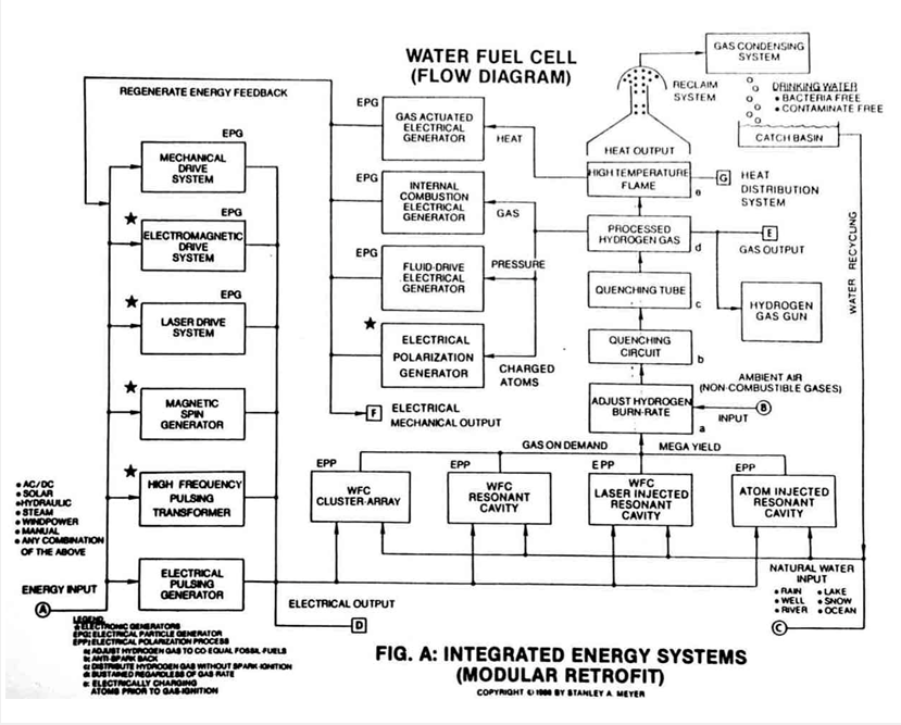
First, high temperatures may be used to power gas-actuated electrical generators.
The high flame heats the gas, which becomes the driving force to power the generator, which in turn creates the electricity for use.
Similarly, heat may be used to create steam to drive generators for electrical production.
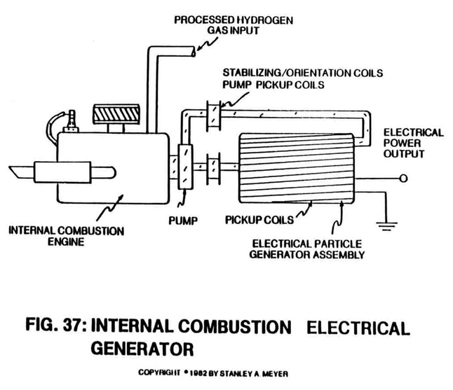
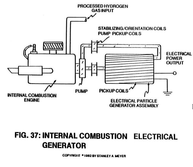
Or, the hydrogen burn rate may be adjusted to co-equal the burn rate of fossil fuels (as previously described) to operate a gas-driven (internal combustion engine) electrical generator.
The gas-driven engine not only provides mechanical to turn the electrical generator, but also manufactures the exhaust gases needed to process the hydrogen gas on demand.
This feedback technique is extremely good since the gas engine requires no special cooling apparatus nor the use of special high temperature alloys or materials for construction.
What does this mean for the consumer?
Remembering that hydrogen by atomic weight is more than two and a half times more powerful than gasoline (NASA test data), and that 2/3rds of a water molecule contains hydrogen, not more than six gallons of water is needed to heat or cool an average 2,000 square foot home (rated at 135,000 per degree day) in a 24-hour period.
Several additional gallons of water are all that is needed to provide home electricity during the same time period.
Also, a few gallons of water is all that is needed to run a typical passenger car in excess of 55 miles per hour.
All the systems may utilize the hydrogen by adjusting the burn-rate downward without sacrificing power yield.
All systems have the capability to recycle hydrogen back into the form of water for energy reuse. See Figure A.
All of the above gas-driven systems are efficient and adequate, and all have common characteristics.
They all have mechanical displacement parts that result in component wear during application.
This may lead to higher operating costs because the lifespan of some mechanical parts may be limited.
In order to provide an even more efficient and reliable energy system that complies with the laws of economics (the person with the least expensive way will be successful).
Meyer has discovered how to create electrical energy without the need for moving mechanical parts.
THE BIRTH OF NEW TECHNOLOGY: THE EPG SYSTEMS:
Meyer has done this by developing the "Electrical Particle Generator” (EPG system).
He contemplated the idea of how to create a device with no mechanical moving parts that could produce electrical energy in all applications.
In order to do this, he knew he had to solve a multiplicity of problems.
He needed to develop a system that conformed to his development specifications for the Fuel Cell.
These specifications would allow the device to be constructed easily and economically, without the aid of hi-tech manufacturing techniques.
He also knew he must make the system reliable, durable and efficient.
He knew he also had to overcome the opposing magnetic field problem that requires high torque (rotational force) power input to operate conventional rotary electrical generators.
EPG: PRINCIPLES OF OPERABILITY:
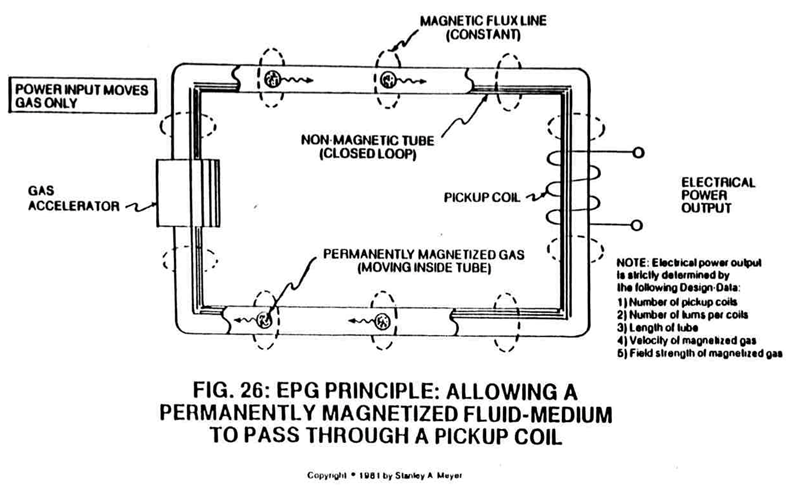
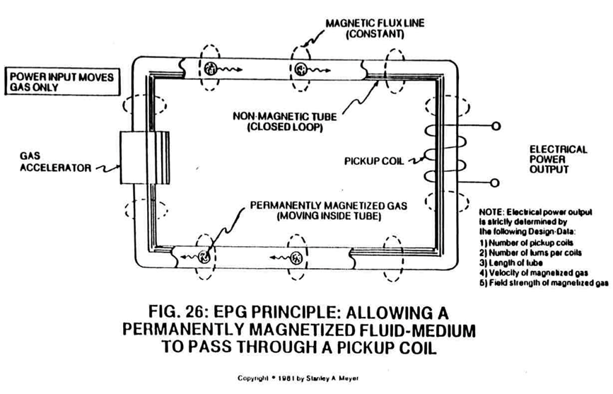 He accomplished the task with the Electrical Particle Generator by moving permanently magnetized gas through a non-magnetic, closed looped, tabular system; see Figure 26.
As it moves, this magnetically charged gas traverses a pickup coil, which generates electrical energy.
This process satisfies the law of physics that states that a magnetic field must pass through a coil of wire for the production of electricity.
Now, the permanently magnetized gas (which actually may be a fluid medium or semi-solid slurry) passes through the closed looped system without interruption.
The energy input into the electrical particle generator is to move the gas, not to create the magnetic field of the gas.
Since the moving gas field is attenuated to minimize the opposing EMF fields of the pickup coils, very little input energy is required to move the magnetized gas.
Power output from the electrical particle generator is simply determined by the coil-wrap of the tube through a given number of coils.
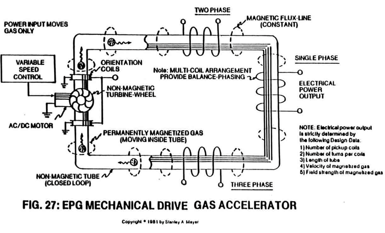
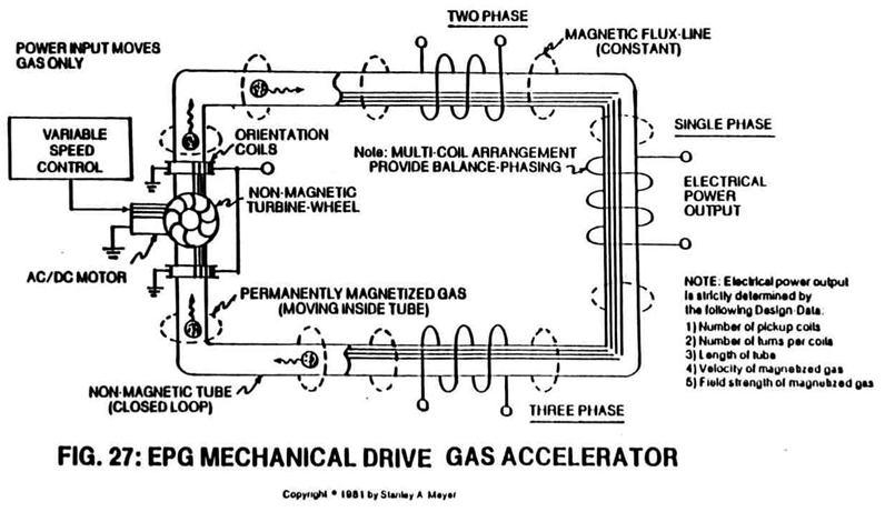
EPG: MECHANICAL DRIVE SYSTEM:
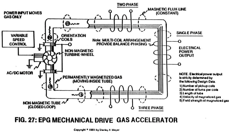 Only a few pounds of pressure is needed to drive the magnetically charged gas through the system.
This may be done mechanically by a small, non-magnetic turbine wheel powered by a small AC or DC electric motor; see Figure 27; or powered by hydraulics, steam, wind power, or even manpower.
But again, moving parts wear out, so this is the least desirable method of moving the gas through the system, despite the fact input to output efficiency of the electrical particle generators exceeds the performance "specs" of typical rotary electrical generators.
EPG: ELECTROMAGNETIC DRIVE SYSTEM:
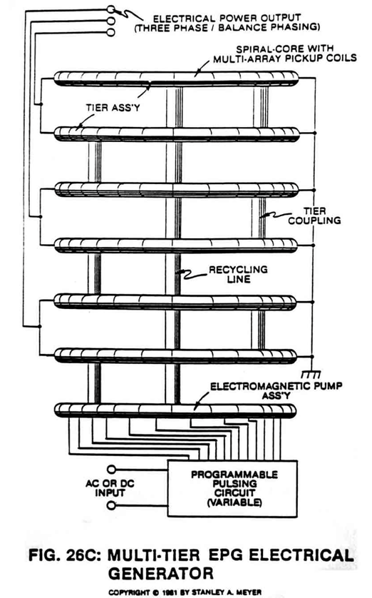
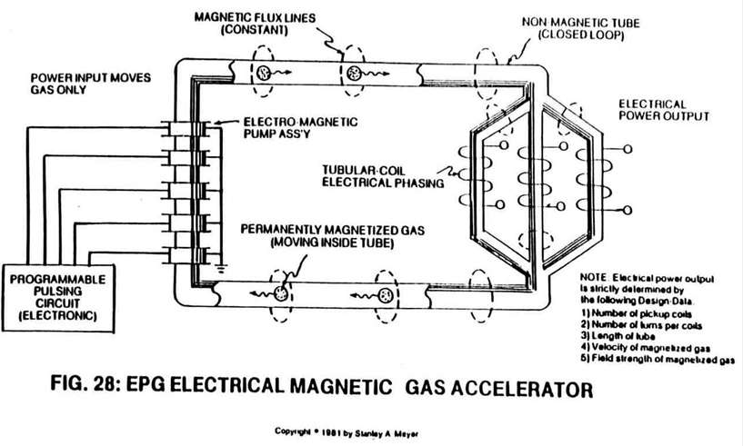
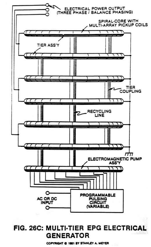
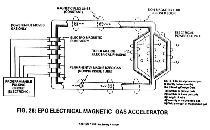
Another way to move the magnetically charged gas through the closed looped system is the use of an Electromagnetic Pump Assembly, as shown in Figure 26C and 28.
The multi-coil arrangement is pulsed in a way as to allow the electromagnetic field to "walk" in a linear motion.
Since the walking fields lock onto the gas, the gas moves onward to and through the pickup coils and is recycled again for continuous power generation.
Increasing pulsing rate increases gas velocity which, in turn, increases power output without system change.
 |
 |
EPG: PARTICLE BEAM ACCELERATORS:
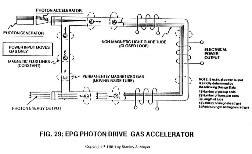
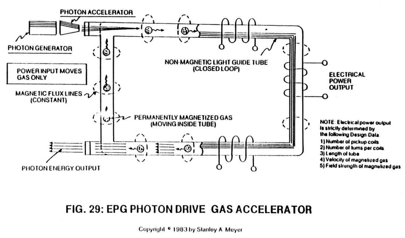 Finally, and most dynamic, is the use of a laser team driven EPG system; see Figure 29.
In this system, the permanently charged particles of gas are driven close to the speed of light through the closed looped system by the physical motion of the low power laser beam.
In this application, the non-magnetic tube is used as a typical light-guide (reflective surface inside a hollow tube).
In other applications, particle beam accelerators beyond the laser can be used for gas displacement...moving the gas-field for electrical power generation.
 EPG: ATTENUATING GAS—FIELD:
In each progression of the above cases, there is an increase in power output because the movement of the gas through the system is greater.
In each case, low energy is required to move the gas through the tubular system.
Because of the flexibility of the system design, it is the geometrical configuration of the system that determines power output.
In all cases, power input deals with moving the gas...not creating an electromagnetic field for the gas.
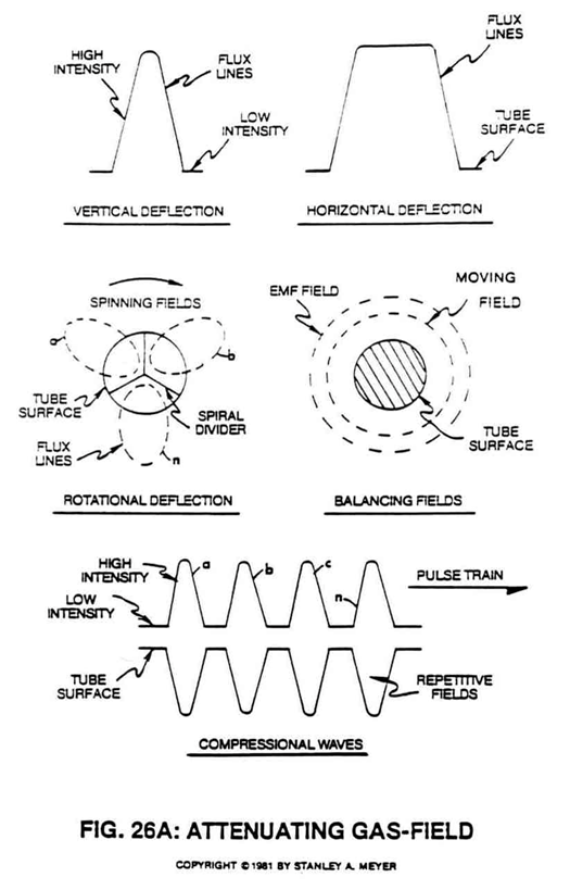
In all cases, the field of the gas can be attenuated in ways to overcome EMF opposition: horizontal to vertical deflection, rotational, compressional wave, and/or field balancing between different magnetic fields, as shown in Figure 26A.
Any combination of these attenuated fields can be used simultaneously while moving the magnetized gas.
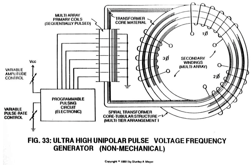
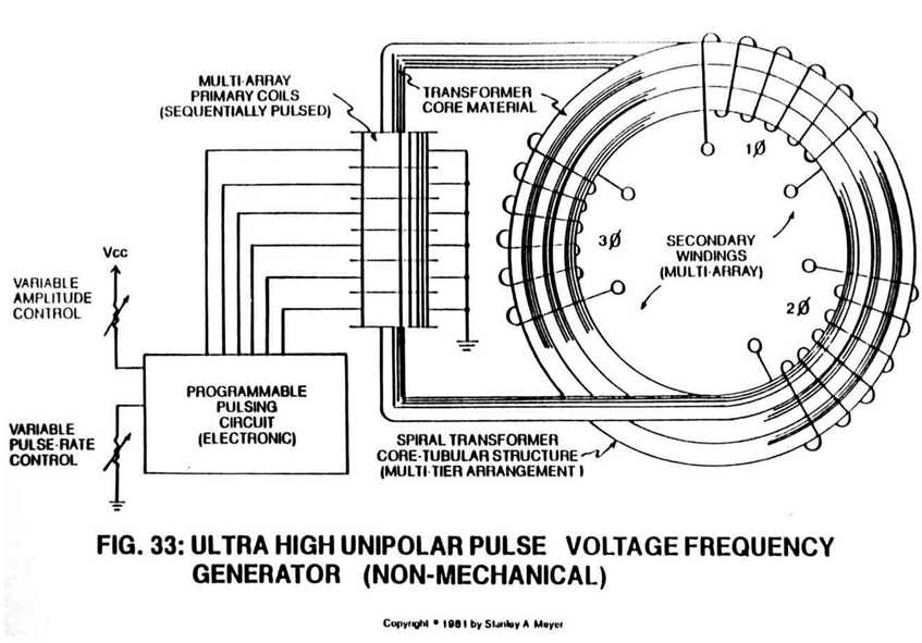
To spin the moving gas along the longitudinal axis of the tube without mechanical displacement, a multi-channel “spiral divider” (see Figure 26A) is inserted into the entire length of the tubular "pathway" (see Figure 33) beyond the gas accelerator stage, as illustrated in Figures 26 through 29.
|
|
|
|
|
|
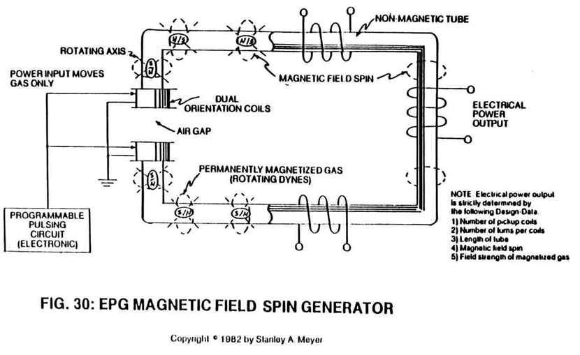
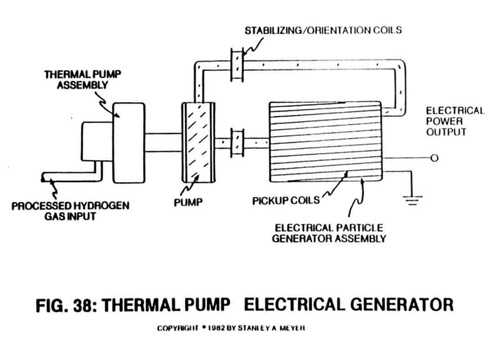
The rotating gas-field can now be varied from a vertical to horizontal movement (magnetic field cycling) by disrupting the dyne-axis (particle alignment) of the permanently magnetized gas (see Figure 30) when orientation coils (see Figures 27, 37 and 38) are used.
 |
 |
Pulsing the orientation coils slowly produces the horizontal movement of the gas-field, whereas a faster pulse rate creates a spike wave form.
The pulsating magnetic fields of the orientation coils simply regulate the particle spin of the gas in a linear motion since "transformer action" cannot occur due to the permanently magnetized gas.
 |
 |
A compressional wave form (Figure 26A) is now produced by superimposing a pulsating pressure onto the spinning gas.
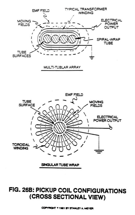
Compounding action (clustering magnetic fields) of the wave forms occurs when the tubular "pathway" (see Figures 26B and 33) is spiraled through the pickup windings.
 |
|
And to help minimize wave form distortion, the EMF field strength is preset (balancing the fields) as to power loading of pickup coils.
These operational parameters help keep the gas velocity constant since the pulsating gas-field can be synchronized with the repetitive formation of the EMF field.
Of course, the oscillating magnetic fields (moving flux lines) transverse the coil windings for electrical power generation.
To cancel out magnetic field loss (magnetic flux lines not being used) during EPG operations, the "transformer" coil-wrap (Figure 26B) is used with the tubular spiral-wrap configuration of Figure 33.
The toroidal coil-wrap (also Figure 26B) is ideally suited for singular tube applications.
Other coil-wrap designs can be used for particular electrical needs.
In all cases, the pickup coils are placed end to end around the portion of the tube beyond the gas acceleration stage, as shown in Figures 26C, 27 through 29 and 33, to form a magnetic coupling of the EMF fields emanating away from the moving gas-field; see Figure 26B again.
 |
|
 |
 |
These concentric magnetic rings allow a magnetic field to pass inside another magnetic field without opposing forces since all of the magnetic flux lines are parallel to each other.
EPG: FLEXIBILITY OF POWER YIELD:
The EPG electrical power output is design-variable since the electrical generators can take on different sizes to meet a given power need.
If additional electrical power is required, simply increase the number of pickup coils.
If more amps are needed, connect the pickup coils in parallel.
If higher voltage is desired, connect the pickup coils in series arrangement.
If a given electrical power yield is contemplated, connect the pickup coils in a series/parallel arrangement to meet the electrical need.
Multi-phasing is simply accomplished by subdividing the coil network to provide proper electrical hookup.
Balance phasing is automatic since the gas velocity remains constant while passing through the entire array of pickup coils.
Pulse phasing of the electrical power output is accomplished by pre-arranging the pickup coils within an array. D.C. pulses occur when the coil arrays are of like turns. A.C. pulses are produced when pickup coils are directly linked to oppositely turned coils of similar design. AC/DC output occurs when both types of coil arrays are wrapped around the same tubular structure in a singular or multi-tier arrangement as shown in Figures 26C and 33.
And finally, to vary electrical power output without system change, simply vary gas velocity. To vary pulse rate output, vary the pulse rate input to the orientation coils.
EPG: MAGNETIC SPIN GENERATOR:
As an alternative to the moving gas approach, the EPG magnetic field spin generator simply rotates the permanently magnetized gas on it’s dyne-axis by pulsing alignment coils, as shown in Figure 30.
The variable pulse voltage frequency input directly determines the power output of the spin generator. Again, the power input into the spin generator is used to realign the permanently magnetized gas, not to produce the magnetic field of the gas.
EPG: OPERATIONAL PARMETERS:
Regardless of the type of EPG electrical generator, the electrical power output is determined by one, or several, or all of the following design parameters:
1) field strength of gas or particle under pressure;
2) gas velocity;
3) number of turns per coil;
4) number of coils;
5) number of tubular wraps per tier (see Figure 33);
6) magnetic field spin (horizontal to vertical deflection, rotational, and compressional wave; and
7) any and all combinations of the above.
The only purpose of the power input into the EPG electrical system is to move, rotate, cycle, and/or attenuate the magnetic field of the magnetically charged Particle-gas under pressure.
By climatizing the EPG system into a water-tight, pressure tight housing, the EPG system can be used on land, under the sea, or in the vacuum of space.
Gravitational forces have no appreciable effect on the operational performance of the EPG generator since the portable power unit is a closed loop system.
FUEL CELL LINKED TO EPG SYSTEMS:
Just as important, the fuel cell can be used to produce electrical energy in several different ways, as illustrated in the energy-grid system of Figure A and pictorially shown in water fuel cell of Figure
The "Q" pipe (or heat pipe) assembly simply transfers heat energy from the sustained hydrogen flame to the thermal gas pump of Figure 38 without any mechanical moving parts.
|
|
 |

The quenching tube distributes the processed hydrogen gas to the gas-engine of Figure 37 without the aid of a gas pump.
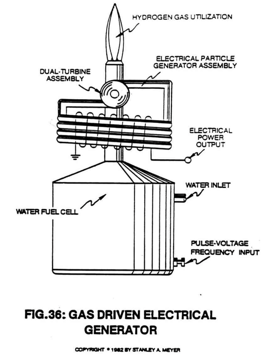
The gas flow pressure from the fuel cell turns the dual-turbine assembly of Figure 36 without altering the combustion property of the gas.
|
Figure 37
|
Figure 36
|
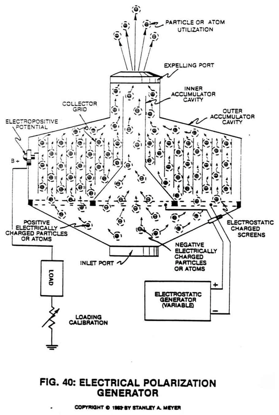
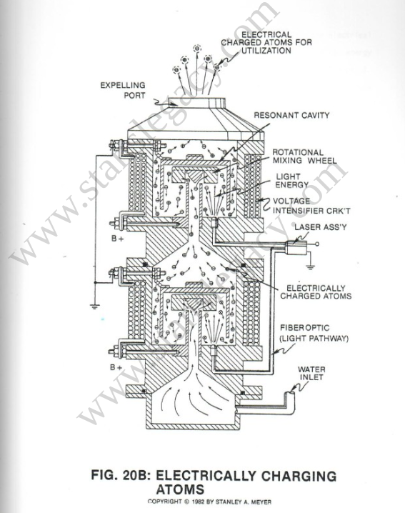
Finally, and most dynamic, the electrically charged atoms of Figure 20B are used in conjunction with the electrical polarization generator of Figure 40 prior to gas ignition.
|
|
|
Whenever a gas powered electrical unit is connected to the EPG network of Figure A, the electrical system hookup is known as a regenerative energy feedback module, as illustrated in Figure B.
|
 |