
Spin Off Technology
In almost all cases of scientific accomplishments, spin-off technology occurs. The Water Fuel Cell is no exception. For every cause there is a reason and for every reason there is an answer and for every answer there is progress. Without scientific progress, we cannot hope to cone with, nor solve, the energy needs of the world. The areas of development below are for that purpose and that purpose only.
TRANSMITTING HYDROGEN THROUGH CONVENTIONAL GAS LINES:
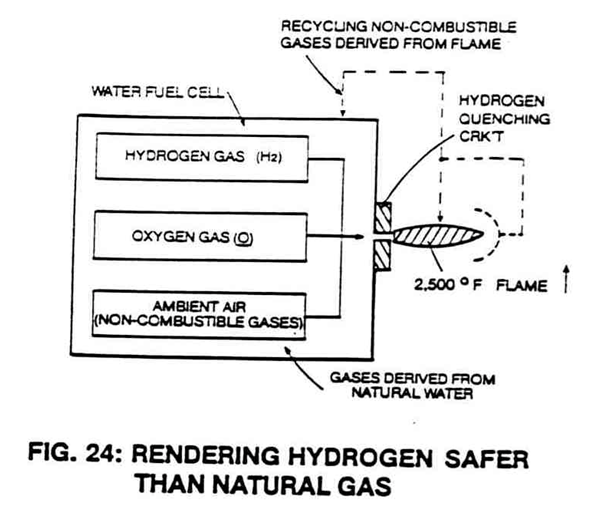
In the area of hydrogen distribution, the quenching circuit technology (see Figure 24) can be altered in a way as to allow hydrogen gas to be transmitted through a standard gas line safer than natural gas, as so illustrated in Figure 31.
This is accomplished in a three-step process.
First, the ambient air is converted into non-combustible gases (non-burnable gases having no oxygen atoms) when exposed to an open flame.
 |
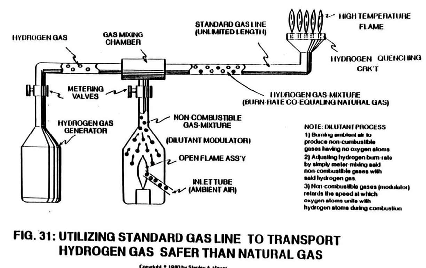 |
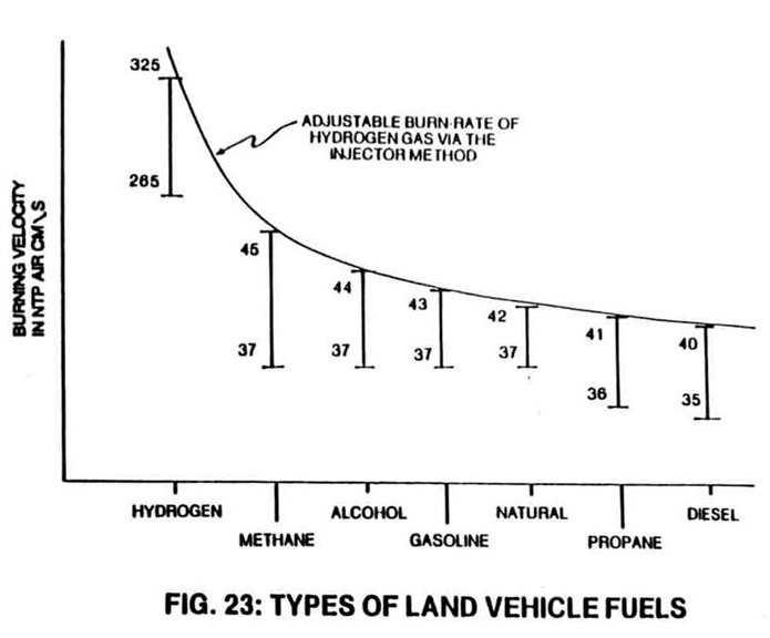 Secondly, the non-combustible gases are systematically mixed with the hydrogen gas to adjust the hydrogen burn rate to co-equal that of natural gas (see Figure 23).
Thirdly, the hydrogen flame is sustained and maintained since the non-combustible gases act as a modulator that retards the speed at which the oxygen atoms (obtained from ambient air) unite with the hydrogen atoms during the combustion process.
Economically, the air conversion cost is almost negligible when considering the fact that a small open flame can convert billions of cubic feet of ambient air (which is free) into non-combustible gases...and especially when the Water Fuel Cell can provide both the open flame as well as the hydrogen gas.
The processed hydrogen gas mixture requires no special handling requirements and can be injected into a conventional gas grid system without the aid of special connectors or other hardware.
STEAM RESONATOR:
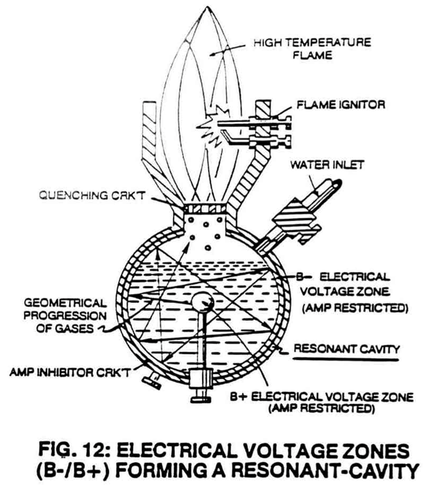
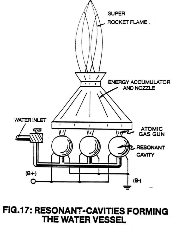
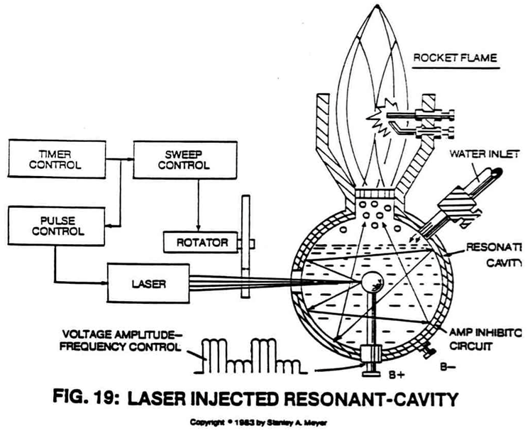
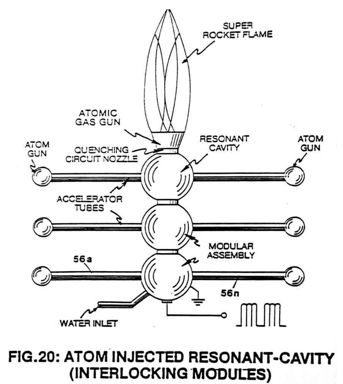
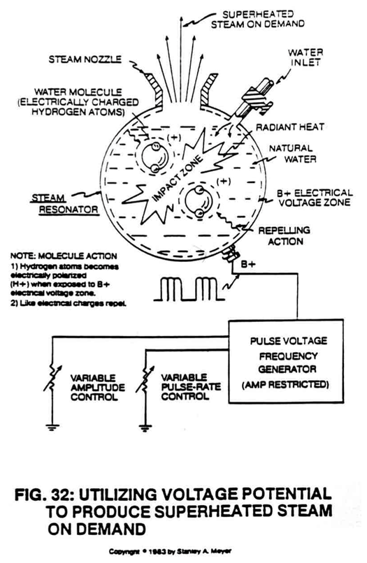 In the realm of steam power, the resonant cavity technique (see Figures 12, 17, 19 and 20) can be combined with the electrical charging of a single atom (one type) of a water molecule to produce superheated steam on demand, as shown in Figure 32.
As the incoming water molecule is exposed to the positive (b+) electrical voltage zone forming the resonant cavity vessel, the hydrogen atoms become positive (b+) electrically charged.
 |
 |
 |
 |
Since like charges repel and cause motion, the accelerated electrically charged molecule (b+ only) collides with the other water molecules, producing heat which is absorbed by the surrounding water.
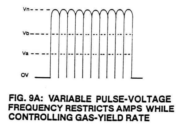
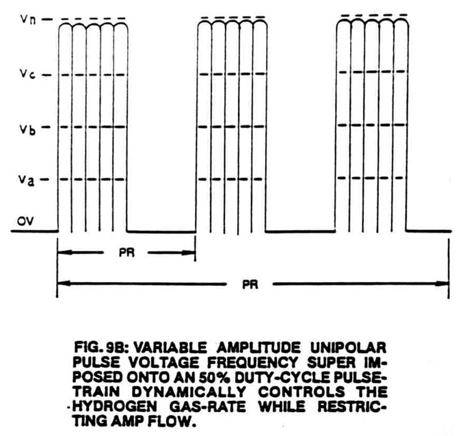
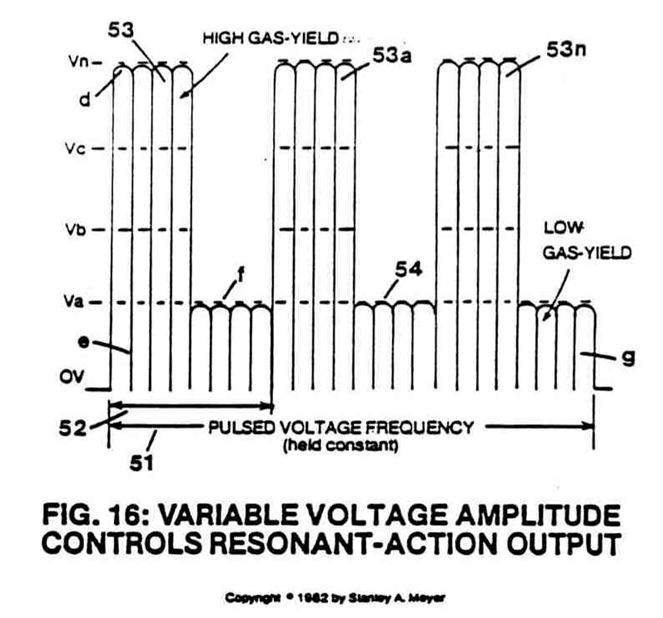
Repetitive formation of the positive (b+) electrical voltage zones (see Figures 9A, 9B and 16) causes instant steam without consuming power in the form of amps.
To further increase steam yield, simply increase the amplitude of the applied pulse voltage frequency potential of a single polarity.
 |
 |
 |
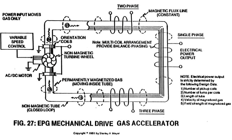
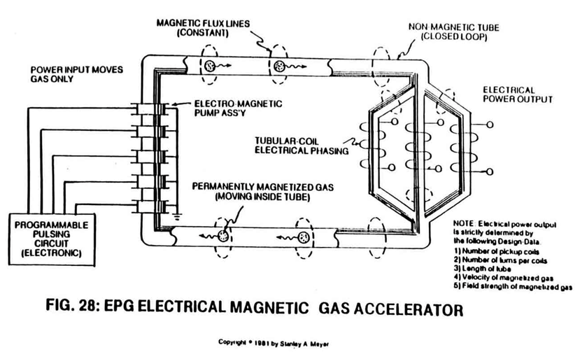
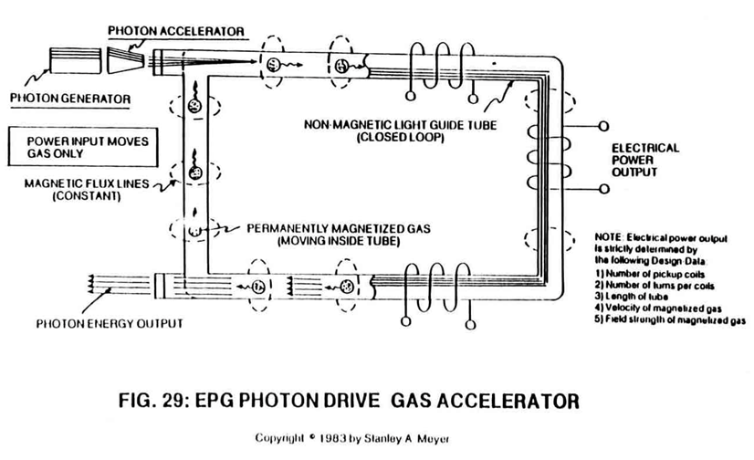
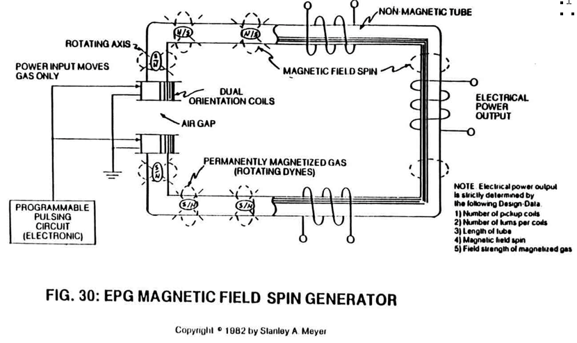
Linked with the EPG systems (Figures 26 through 30), or with the pulse voltage frequency generators shown in Figures 33 and 34, the steam resonator (Figure 32) can be directly retrofitted to any power plant using steam as power.
No fossil fuels or other burnable additives are needed in the process.
 |
 |
 |
 |
 |
 |
 |
 |
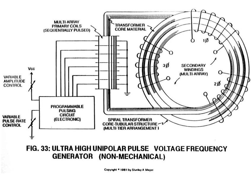
HIGH FREQUENCY PULSING GENERATOR:
In special areas of power applications, the non-mechanical pulse voltage frequency generator (See Figure 33) can be utilized where ultra high pulse frequency is needed without sacrificing lower yield.
The multi-array primary coils overcome the pulsing limitation of a single coil; whereas the spiral transformer core (hollow structure) reduces the magnetic field loss between the primary and secondary windings.
The multi-tier arrangement allows for multi-power applications.
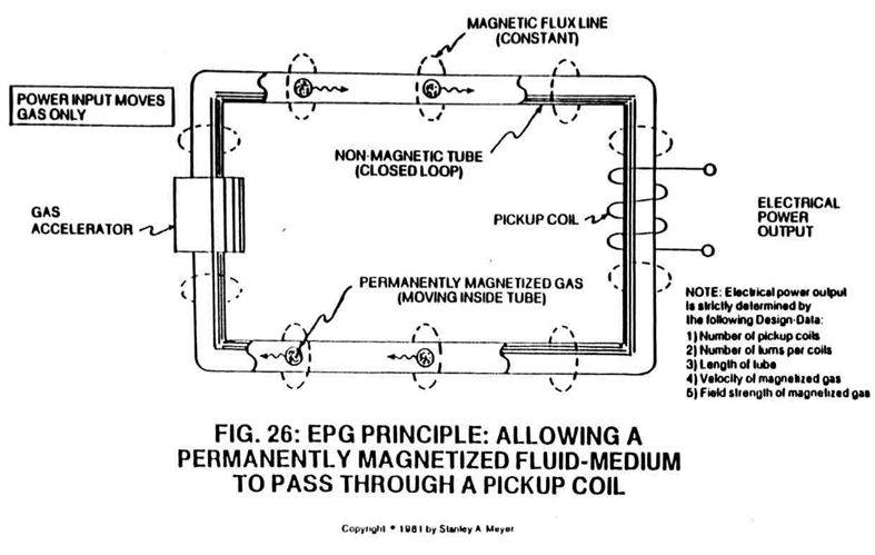
To help maximize power loading efficiency, the spiral tubular core configuration (Figure 33) is also incorporated into the design of the EPG electrical system (Figures 26 through 30).
The spiral core configuration is also instrumental in providing balance phasing between any given number of pickup windings.
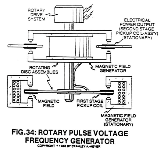
ELECTRICAL PULSE GENERATOR:
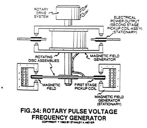
To further facilitate flexibility, the Electrical Pulse Generator (Figure 34) was primarily developed for special applications, such as for grain drying or for regenerative energy feedback systems.
The rotating first and second stage pickup coils allow the magnetic field strength of the first magnetic field circuit to be increased in the second magnetic circuit...
increasing power Output without the aid of contact brushes.
LIGHT GUIDE LENS ASSEMBLY:
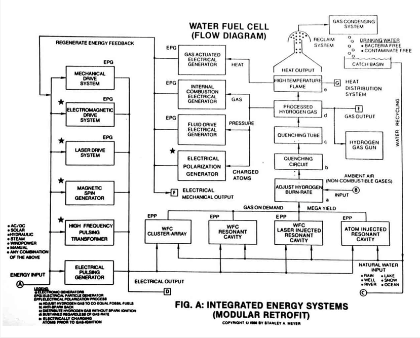
S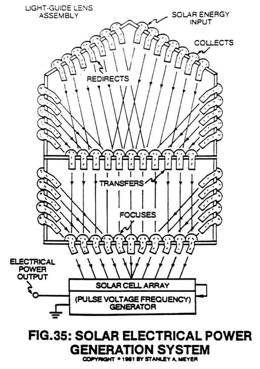 olar energy input into the energy grid system (Figure A) can be obtained by utilizing a Light Guide Lens Assembly, as shown in Figure 35.

The cylindrical "wall" lens, focusing and transfer lenses, and capping lens form a unitized silo structure that collects, redirects, transfers and focuses the light energy without any moving parts, regardless of the sun position during the daylight hours or seasons.
The concentrated solar energy can either be stored or converted into electrical energy by high-yield solar cells.
The solar lens operates on the fiber-optic principle.
GAS DRIVEN ELECTRICAL PARTICLE GENERATOR:
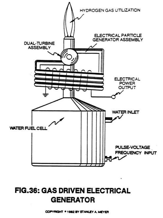 Combining the Water Fuel Cell with the Electrical Particle Generator, as shown in Figure 36, further aids the energy grid system (Figure A) as to energy feedback by coupling a dual turbine wheel assembly to the quenching nozzle of the Fuel Cell.
As the gas is generated and expelled through the gas nozzle, the moving gas turns the first stage turbine, which drives the second stage turbine that propels the magnetized gas for electrical power generation.
This process does not convert the generated gases in any way...it only utilizes the pressure of the gas to perform work during Fuel Cell operations.
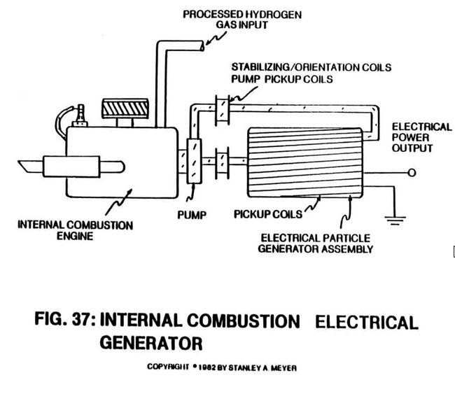
INTERNAL COMBUSTION ELECTRICAL GENERATOR:
Another regenerative energy feedback network is formed when the Electrical Particle Generator of Figure 37 is retrofitted to any type of internal combustion engine.
The engine mechanical drive train is affixed to the EPG turbine that propels the magnetized gas for electrical power generation.
Since the hydrogen gas burn rate co-equals gasoline, the engine gas-fuel is directly supplied by the Fuel Cell in Figure A.
This process simply utilizes the combustion property of hydrogen gas rather than the movement of the gas.
 |
 |
THERMAL PUMP ELECTRICAL GENERATOR:
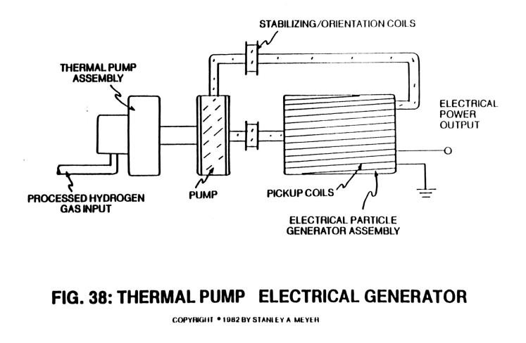
The Thermal Pump Electrical Particle Generator of Figure 38 operates on the third aspect of the hydrogen gas, which is heat.
The sustained hydrogen gas flame of Figure A provides the heat energy input to drive the thermal pump assembly, which in turn provides torque power to the EPG turbine assembly.
Beyond the gas conversion process, the EPG turbine assembly can be affixed to portable windmills or compressed air systems for EPG operations.
ELECTRICAL POLARIZATION GENERATOR:
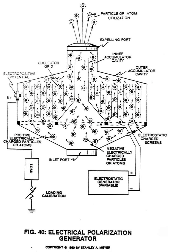 To complete regenerative energy grid of Figure A as to Water Fuel Cell of Figure B, the electrical polarization generator of Figure 40 is utilized to capitalize on the fourth aspect of a gas, which is gas ionization.
As illustrated, a stream or group of positive electrically charged atoms on a surface causes the collector-grid surface to be positive charged, which in turn makes the terminal post positive charged since said terminal post is affixed to said collector-grid.
As more charged atoms are entrapped within said collector-grid, said terminal potential increases until gas flow rate becomes constant.
Once an electrical load is placed between said positive terminal post and electrical ground and electric current-performs work as to load capacity.
The electrostatic charged screens attract more charged atoms continue the electrical performance of said generator.
In essence, said electrical polarization generator (Figure 40) requires no chemical interaction nor moving parts since the moving electrons combined with the moving charged atoms prior to secondary atom utilization beyond the expelling ports.
If required, negative electrical potential is generated by allowing negative electrically charged atoms to pass through the inner accumulator cavity.
HYDROGEN GAS RECLAIM SYSTEM: WATER PURIFICATION:
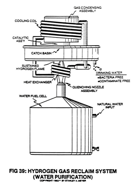 As explained in Section Six and as illustrated in Figure 39, the hydrogen gas reclaim system renders hydrogen environmentally safe.
In actuality, the reclaim system is a water purification system that has the capability of extracting both contaminants and bacteria from natural water without the aid of chemical additives or special filtration systems.
The water purification process is quite simple: the electrical polarization process splits the water molecule to form a gas mixture that sustains a hydrogen flame during combustion and produces water vapor.
Contaminants that are no longer stored between the splitting water molecule are systematically discarded from the Fuel Cell.
If any bacteria in water affix themselves onto the expelling gas the high temperature flame simply incinerates them.
The catalytic block assembly ensures the complete combustion of the hydrogen gas, and the catch basin simply collects drinking water free of all contaminants, bacteria and chemical toxicity.
This system is ideally suited for desalination of ocean water for desert irrigation. Mineral extraction from water is another application.
THE WATER FUEL CELL TECHNOLOGY ANSWERS THE QUESTION:
The Water Fuel Cell technology is a composite of many systems integrated together for a common purpose...
providing a practical answer to the energy problem.
The hydrogen age can now replace the fossil fuel era.