

patent · US3876892A
Commutating structure for dc permanent magnet machines
8 April 1975
Text
Page 1bibliographic recordscan →
United States Patent (19) (11 3,876,892 Noodleman (45) Apr. 8, 1975 (54) COMMUTATING STRUCTURE FOR DC 3,544,868 12/1970 Bates.............................. 310,231 X PERMANENT MAGNET MACHINES 3,603,823 9/1971 Mason...... ...... 310/46
(75) Inventor: Samuel Noodleman, Blacksburg, Va.
FOREIGN PATENTS OR APPLICATIONS
Assignee: storgen Corporation, Hartford, l,065,579 5/1954 France................................ 310/219 22 Filed: May 20, 1974 Primary Examiner-Donovan F. Duggan (21) Appl. No.: 471,313 :gly,
Agent, or Firm-Morgan, Finnegan, Durham
Related U.S. Application Data 63 Continuation-in-part of Ser. No. 383,883, July 30, 1973, Pat. No. 5. y 57 ABSTRACT
A DC permanent magnet machine in which the func 52 U.S. Cl. ................... 31046; 310/219; 310/128 tions typically attributed to the stator and rotor assem (5ll Int. Cl. ........................................... H02k 13100 blies are reversed to provide an "inside out" design. Field of Search...... 30/40R, 40 MM, 46, 152, The stator is provided with a plurality of electrically 310/156, 219, 231, 238, 248, 128 energizable poles having windings which are electri cally coupled to associated commutator bars forming References Cited an annular array. Also associated with the stator are a UNITED STATES PATENTS pair of annular conductive rings. The rotor is provided 388,513 8/1888 Van Gestel 310,219 with a plurality of permanent magnet poles equal in 399.329 3 fis89 Heywood. 31012 9 number to the poles provided in the stator. The rotor 1375.61 4/1921 Landers. 31 0129 also carries a plurality of roller contacts which serve 2, 1942 l 3/1940 Sansom............................. 31046 x to couple the commutator bars to the conductive rings 2,409,600 10/1949 Trautschold..... ... 3101219 which are, in turn, connected to opposite polarities of 2,467,758 4/1949 Lindenblad...... ... 310/219 X the DC energizing source, thereby providing electrical 3,341,726 9/1967 Brinster et al.................. 310/219 X power to associated coils of the stator winding. 3,396,296 8/1968 Esters............................... 31046 X red 3,534,203 10/1970 Sommeria......................... 31 0146 X 6 Claims, 7 Drawing Figures
Ases
'S VSY
Drawings
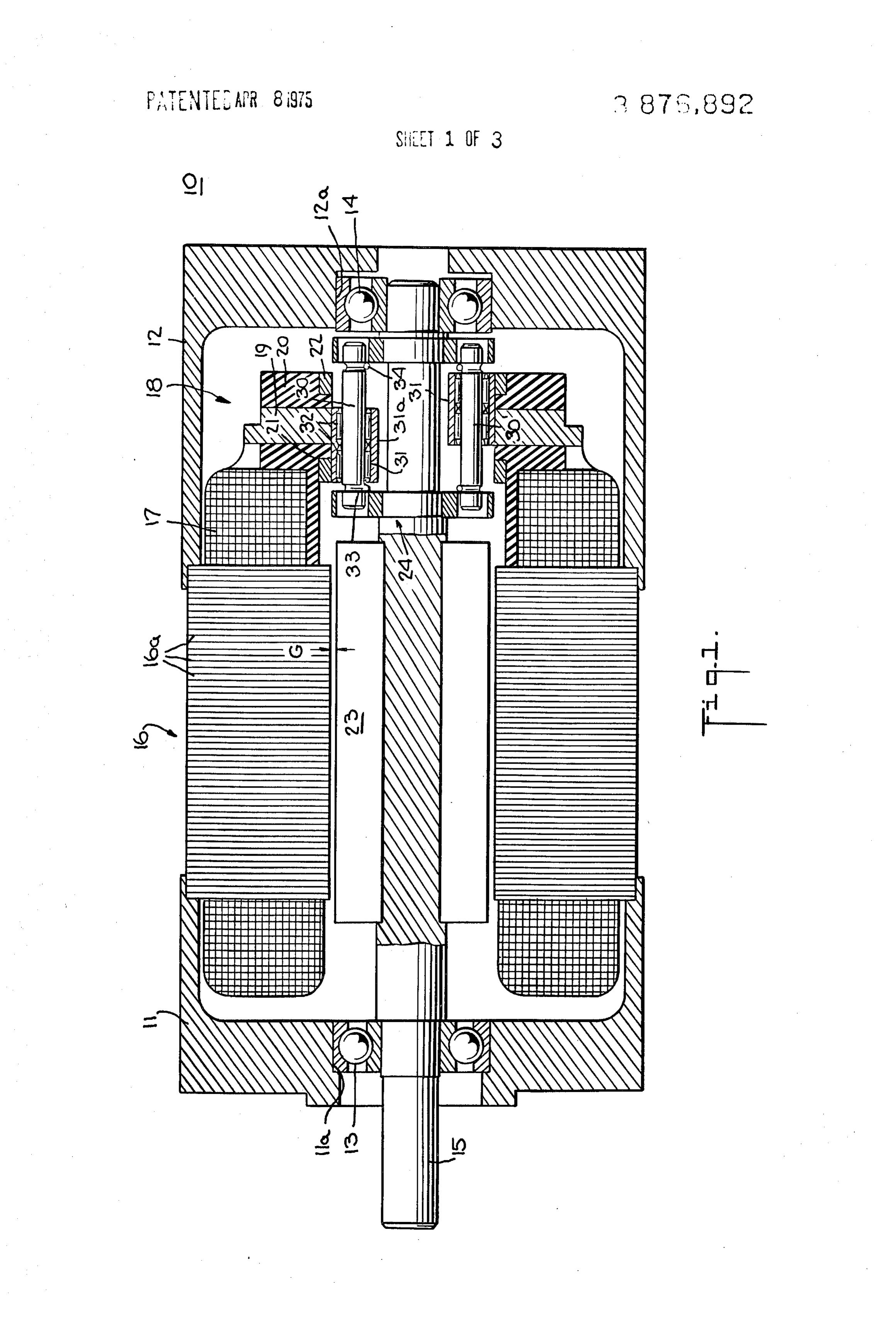
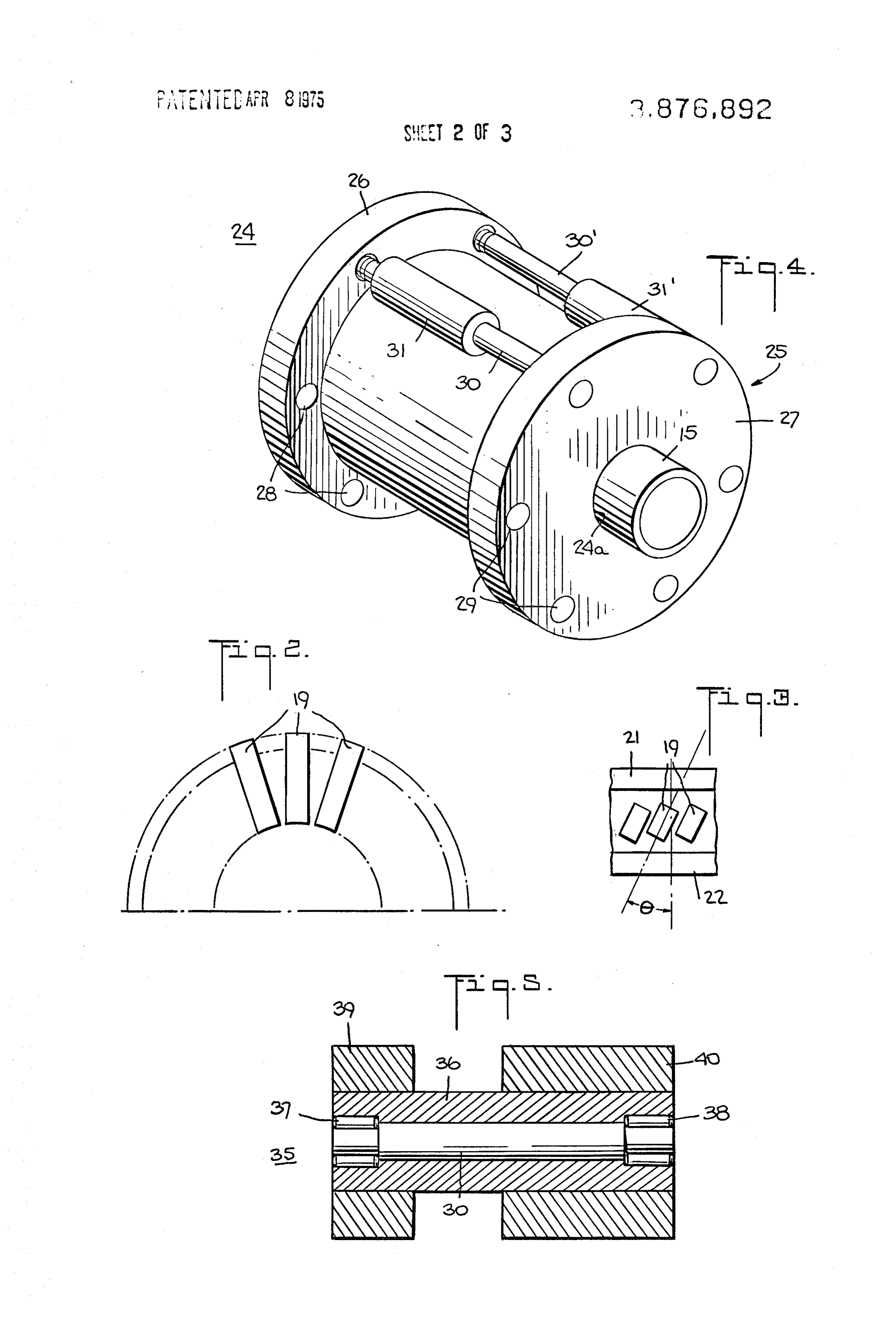
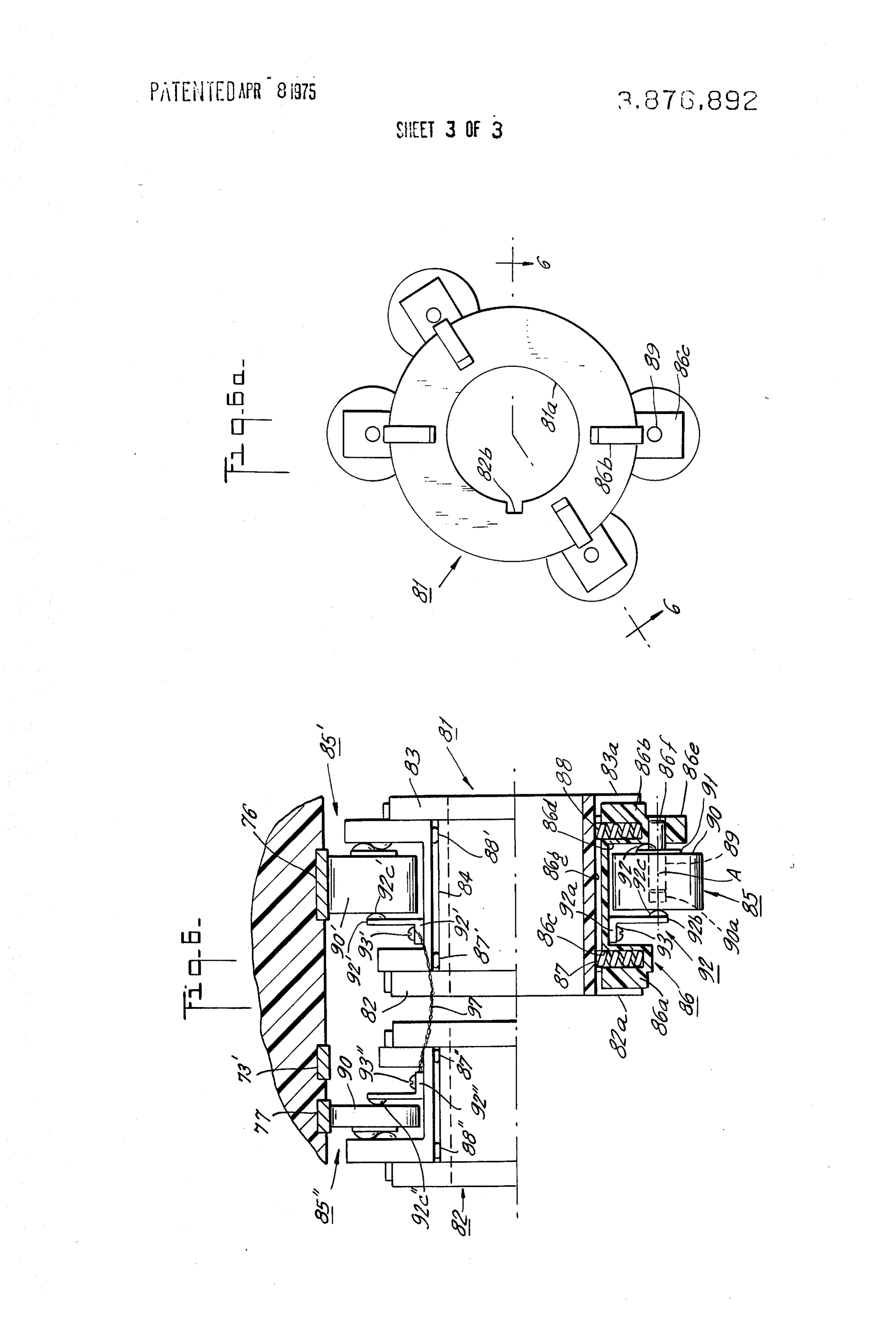
FIG. 6a shows an end view of the embodiment of 15 Roller contact 31 is positioned along shaft 30 so as to make continuous rolling engagement with conduc
Page 2drawing sheetscan →
Page 3drawing sheetscan →
Page 4drawing sheetscan →
Page 5scan →
COMMUTATING STRUCTURE FOR DC opposite polarities of the DC source so as to progres PERMANENT MAGNET MACHINES sively energize stator coils, the magnetic fields of which interact with the rotating magnetic fields of the rotor
This application is a continuation-in-part of applica permanent magnets to effect rotor rotation. tion Ser. No. 383,883 filed July 30, 1973, now U.S. Pat: 5 Thus, conventional commutation, in which brush and No. 3,819,964. commutator wear is caused both by sliding friction and BACKGROUND OF THE INVENTION the burning action of commutating current, is replaced by the rolling contact between the conductive rings and
DC motors of conventional design typically utilize a the commutator bars. This novel commutation tech multi-pole permanent magnet stator and a rotor having 10 nique permits the motor components to be designed for a plurality of energizable conductors arranged about optimum commutation, minimum wear and smooth op the surface thereof and parallel to the axis of rotation. eration.
Pairs of said conductors are electrically energized by The aforeside unique commutation method is, of rotating commutator bars provided on the rotor, which course, also adaptable for use in conventional DC commutator bars are electrically energized by a DC 15 motor design wherein the annular arrays of commuta source through stationary commutator brushes which tor bars and conductive rings are incorporated in the make wiping engagement with the commutator bar ar rotor design and the roller contacts form part of the sta ray. Interaction of the stator permanent magnet fields tor.
with the magnetic fields created by DC energization of The commutating technique of the above design ex the rotor conductors provides for rotation of the rotor, 20 emplified by copending application Ser. No. 383,883 whereby relative rotation of the commutator bars and employs a "rigid' roller concept in which the rollers commutator brushes continuously changes the electri contacting their associated slip rings and the rollers on cal connections between the DC source and the array the commutator are mechanically as well as electrically of conductors in the rotor. Significant wearing of the tied together so that current brought in through the slip commutator bars is caused both by the sliding friction 25 ring roller is fed directly into the commutator roller. of the brushes and the burning action of the commutat Whereas this approach provides minimum contact ing current, thereby reducing the useful operating life drop, it also requires that the associated rollers be oper of the motor. ating at the same speed. Consequently, any factors The above disadvantages, as well as the fact that con which result in the production of differing roller or ring ventional DC motors have high inertia, has led to the 30 diameters or any other condition which would cause development of the "inside out' motor design in which one of the rollers to operate at a different speed would the multi-pole rotor is provided with permanent mag impose upon its associated roller the requirement that net members and the stator is provided with an equal it must slip with respect to the other. Also, if after long, number of poles whose windings are energized by the continued use, one of the rollers wears at a rate differ DC source. This design provides a rotor with lower in-3 ent from its associated roller causing its diameter to ertia for a given peak torque, and a stator having change, slippage will occur. It has also been found that greater copper volume and better heat dissipation as a structure mechanically tying two rollers together in compared with conventional DC motor designs. Thus, troduces dynamic instability in that the moment of in the "inside out' motor design has a higher continuous 40 ertia of the roller assembly about an axis at right angles rating in contrast to conventional DC motors of the to the axis of rotation is quite high and any bounce or same size and weight. eccentricity is greatly magnified at high rotating speeds The problems of commutation in motors of the "in which can cause the rollers to pull away from the con side out" type has led to the development of a DC tacting surfaces.
brushless type motor which employs electronic amplifi ers and other solid state circuit elements to provide the 45 BRIEF DESCRIPTION OF THE INVENTION necessary commutation. The electronic amplifiers and A novel roller design for use with the above circuit elements required for proper switching of power described commutating structure has now been devel to the stator windings to generate the rotating field add oped whereby each roller is spring loaded against its significant cost and weight to the motor. The solid state mating surface and therefore can operate indepen switching circuitry also increases motor "cogging' 50 dently of the other. Both of the associated rollers and which occurs during low speed motor operation. the contact spring arrangements which conduct current The numerous problems and disadvantages encoun therebetween are mounted upon separate and indepen tered in DC motors of both the conventional and "in dent spring biased assemblies which include a "split’ side out" design has led to the development of the de 55 spring contact arrangement with separate halves of the sign described in the aforementioned copending appli spring contact arrangement mounted upon each slider. cation which is characterized by providing novel elec The present invention provides a novel contact ar tro-mechanical switching techniques for commutating rangement for use in DC permanent magnet machines the motor windings. and the like, especially of the "inside out' design, In a preferred embodiment of the invention disclosed 60 wherein each roller assembly utilizes independently in the above-mentioned copending application, the sta mounted spring biased roller contacts which, while tor assembly is provided with first and second annular being electrically connected to one another, are inde conductive rings connected to opposite polarities of a pendently movable so as to enhance dynamic stability DC source and an annular array of commutator bars of the switching assembly and so as to permit indepen disposed proximate thereto. The rotor assembly is pro- 65 dent operation of each roller. vided with a plurality of roller contacts which revolve BRIEF DESCRIPTION OF THE DRAWINGS with the rotation of the rotor shaft to simultaneously couple the opposite terminals of the stator coils to the The invention is set forth in greater detail in the spec 6 ification of which the following drawings form a part: spaced openings 28 and 29. The openings of the array FIG. 1 is a sectional view of a preferred embodiment in flange 26 are opposite the associated openings of the of the invention; array in flange 27 and are adapted to receive a shaft 30 FIG. 2 is a partial sectional view of the commutator which is secured therein so as to experience no rotation bar array of FIG. 1; about its longitudinal axis.
FIG. 3 is an interior radial view of the commutator Referring once again to FIG. 1, a roller contact 31 is bar array of FIG. 1; rotatably mounted upon shaft 30 by bearings 32. Roller FIG. 4 is a perspective view of the roller contact as contact 31 is preferably formed of a suitable contact sembly of FIG. 1; material such as electrographitic carbon, carbon graph FIG. 5 is a sectional view of a roller contact which O ite, silver graphite, silver cadmium oxide or silver tung may be used with the embodiment of FIG. 1; sten. While roller contact 31 is free to rotate about FIG. 6 is a side view of one preferred embodiment of shaft 30, bearing 32 has its inner face secured to shaft the roller contact assembly shown in FIG. 1 and incor 30 to prevent contact 31 from moving linearly along porating the principles of the present invention; and shaft 30.
FIG. 6a shows an end view of the embodiment of 15 Roller contact 31 is positioned along shaft 30 so as to make continuous rolling engagement with conduc
DETAILED DESCRIPTION tive ring 21 and sequential and progressive engagement FIG. 1 shows a preferred embodiment 10 of the in with the radial array of commutator bars 19. A second roller contact 31' is associated with roller vention which is comprised of housing members 11 and 20 contact 12 which are each provided with openings 11a and 12a around 31 drum and is positioned a spaced angular distance 25. Roller contact 31' is rotatably for receiving bearing 13 and 14 which surround a rotat mounted to a shaft 30' by bearings similar to bearings ably mounted rotor shaft 15. The inner ends of housing 32. Roller contact 31' in addition to being angularly members. 11 and 12 are hollow and are contoured or otherwise formed to receive and support the stator and relative to roller contact 31 so31, 25 displaced from roller contact is linearly displaced to make continuous rotor assemblies.
rolling contact with conductive
The stator assembly is comprised of a laminated core make sequential and progressive rolling ring 22 as well as to 16 formed of individual laminations 16a. The stator engagement winding is comprised of a plurality of coils 17 (not with commutator bars 19.
shown in detail for purposes of simplicity) which, when 30 andThe31'angular displacement between roller contacts 31 energized, create magnetic fields in the stator core neously engage athat is such the roller contacts will simulta pair of displaced commutator bars which interact with the magnetic fields set up in the which are connected to the end terminals of a common rotor assembly to effect rotor rotation. stator coil to couple opposite polatiries of the energiz Housing member 12 is further adapted to receive the commutator assembly 18, which includes a plurality of 35 ing source thereto. Although not shown for purposes of commutator bars 19 mounted in radial fashion (see simplicity a number of pairs of roller contacts are ar FIG. 2), within an annular-shaped insulating member ranged around drum 25 for electrically energizing a 20. Selected ones of the commutator bars are electri like number of coils to develop magnetic fields in the cally connected to the remaining terminal of associated 40 stator which interact with the rotating magnetic fields stator coils. As shown in FIG. 3, the commutator bars the of the rotor permanent magnets to sustain rotation of 19 are aligned at a small angle 0 with respect to each rotor shaft.
other so that a roller contact moving left to right with Shaft 30 is biased at each end by springs 33 and 34 respect to FIG. 3 will effect a make-before-break to urge roller contact 31 into firm electrical engage contact with the commutator bars. In addition, skewing 45 ment with the associated conductive ring and commu the commutator bars provides a smooth rolling surface tator bars. As the angular velocity of the rotor shaft in for the roller contact so that it will mate smoothly with creases, the centrifugal force created serves to assist the inside surface of the commutator. springs 33 and 34 in providing good electrical contact. A pair of conductive rings 21 and 22 are mounted FIG. 5 shows an alternative roller contact assembly within grooves provided in annular-shaped insulating 50 35 for use with the embodiment of FIG. 1 comprising member 20 and positioned on opposite sides of the a tubular conductive member 36 rotatably mounted to commutator bar array. Conductive rings 21 and 22 are shaft 30 by bearings 37 and 38 which are secured respectively connected to the plus and minus terminals within grooves provided in conductive member 36 and of the DC source (not shown). While shown in FIG. 1 shaft 30, as disposed on opposite sides of the commutator bar 55 A first, shorter sleeve 39 is secured to conductive array 19, both conductive rings 21 and 22 may be posi member 36 and is positioned to make contact with one tioned on the same side of the commutator bar array if of the conductive rings 21 and 22. Sleeve 39 may pref desired. erably be formed of a suitable contact material such as The rotor assembly comprises a permanent magnet electrographitic carbon or silver graphite. A second array 23 secured to shaft 15. The outer periphery of the longer sleeve 40 is secured to member 36 a spaced dis permanent magnet array lies a small, spaced distance 60 tance from sleeve 39 and makes contact with the com from the interior periphery of the stator core 16 to mutator bars 19. Sleeve 40 is also preferably formed of form a hollow, annular-shaped gap G therebetween. a suitable contact material such as electrographitic car Referring now to FIG. 4, there is shown a roller bon or silver graphite. The use of two separate sleeves contact assembly 24 comprising a cylindrical drum 25 65 enables selection of materials which are best suited for secured to shaft 15 by means of a central opening 24a. the particular application.
The ends of drum 25 are provided with integral, formed In operation, the current in the sleeve engaging con annular flanges 26 and 27 each having an array of ductive ring 21 (or 22) passes through conducting 7 member 36 and sleeve 40 so as to be selectively and progressively transferred to the commutator bars 19. It is generally accepted that energizing windings uti lizing the DC brushless concept requires: relatively large numbers of solid state components in an elec 5 tronic control circuit in order to develop the effect of the large number of commutator bar segments which are necessary for smooth operation at slow speeds. In view of the foregoing, another application of the pres ent invention is to use the commutation techniques de 10 scribed herein to effect a smooth DC brushless motor operation at slow speeds and then switch to a static control incorporating a smaller number of solid state circuit elements to energize the windings during high speed operation. Such an arrangement would serve to 15 provide a smooth operating motor at slow speeds and to provide the long life operation of the DC brushless control circuit for high speed conditions.
As can best be seen from a consideration of FIGS. 1 and 4 the roller contact 31 mounted upon shaft 30 has 20 a length sufficient to enable the roller contact to simul taneously engage conductive ring 21 and the surfaces of commutator bars 19 (see FIGS. 2 and 3). If there be any uneveness in the wearing of the surface portion of the roller 31 which engages the conductive ring 21 rela 25 tive to the wearing of the portion of roller contact sur face 31 which engages the commutator bars 19, slip page will occur or, alternatively, the faster wearing sur face will not make sufficient contact with its engaging 30 contact surface. In the embodiment shown in FIG. 5, where separate roller portions 39 and 40 are mounted upon a hollow cylindrical member 36, uneven wearing of the surfaces of the members 39 and 40 will create similar problems.
In order to overcome these remaining difficulties the 35 switching assembly of FIGS. 6-6a has been developed. As shown therein, separate roller assemblies are uti lized so that the entire assembly is free to maintain rol ler contact against the commutator bars and conduc 40 tive rings.
As shown in FIG. 6a, first and second drums 81 and 82 are provided. Each of these drums is provided with a central opening such as, for example, central opening 81a, which opening is used for mounting the drum as 45 sembly upon rotor shaft 15. Considering FIG. 6, drum 81 is provided with continuous, annular flanges 82 and 83 spaced apart by a cylindrical surface 84 of reduced diameter. Flanges 82 and 83 are each provided with rectangular shaped slots 82a and 83a for slidably re ceiving end portions 86a and 86b of a slider member 86 50 which is slidably mounted within the aforementioned rectangular shaped slots. Slider 86 is further provided with first and second circular-shaped bores 86c and 86d for receiving helical springs 87 and 88, respectively, 55 which are positioned between the bases of bores 86c and 86d and the surface 84 of drum 81. An outwardly extending rectangular shaped portion 86e of slider 86 is provided with an opening 86f for force fitted pin 89 which extends toward the left as shown in FIG. 6 to be 60 inserted into an opening 90a in conducting roller 90. A washer and leaf spring 91, having a serpentine configu ration, are positioned between the projection 86e of slider 86 and the right-hand surface of roller 90. An L-shaped contact spring 92 has one arm 92a se 65 cured to the base 86g of slider member 86 by fastener 93. Arm 92b is provided with a contact button 92c which bears against the lefthand surface of conducting roller-90. Contact, button 92c engages the surface of conducting roller 90.at a point which is coincident with both the longitudinal axis of pin 89 and the rotating axis of conducting roller.90. Roller assembly 85", shown in the upper portion of FIG. 6 is substantially identical to roller assembly 85 and cooperates with another roller assembly 85' mounted upon drum 82 and substantially identical in design to roller assemblies 85 and 85’ ex cept that conducting roller 90''. is shorter in axial length than rollers 90 and 90'. The fastening members 93' and 93', in addition to serving as a means for se curing contact springs 92' and 92' to drums 81 and 82, further serve as a means for securing the respective ends of a conductive lead 97. . .. .
Considering roller assemblies 85': and 85', conduct ing roller 90 progressively rollingly engages the com mutator bars 76 while conducting roller 90' rollingly engages conductive ring 77, whereby the electrical path extends from one terminal of the DC source to conductive ring 77, conducting roller 90', contact but ton 92c', contact spring 92', conductive lead 97, contact spring 92', conductive button 92c', conducting roller 90' and the commutator bars 76. It should be un derstood that both drums 81 and 82 may be provided with keyways for locking drums 81 and 82 to rotor shaft 15 to prevent any rotation of the drums relative to shaft 15. Similar pairs of roller assemblies are pro vided for conducting DC energy of the opposite polar ity from conductive ring 73' to the commutator bars
The arrangement of the contact assembly of FIGS. 6-6a provide operating characteristics which embrace all of the advantages of the commutating structure of F.G. 1 as well as providing enhanced dynamic stability. The novel DC motor described herein, in contrast to conventional DC motors, permits the use of a rotor as sembly having a relatively small mass and a corre sponding low moment of inertia. Moreover, the perma nent magnet members may be of the ceramic type to further reduce the mass of the rotor assembly. Effect ing commutator switching in the stator assembly per mits the use of a larger copper volume which signifi cantly reduces the amount of heating occuring in the electrically energized stator assembly, which serves to prolong the useful operating life of the motor. Also, having the windings in the stator eliminates the stress normally experienced by rotor-mounted windings, thereby prolonging the life of the windings and the mo tor. By the use of the contact assemblies of FIGS. 6-6a the DC machine design embraces all of the aforemen tioned advantages as well as that of greatly enhancing the dynamic stability of the device.
The invention disclosed and claimed herein is not limited to the specific mechanism and techniques herein shown and described since modifications will undoubtedly occur to those skilled in the art. Hence, departures may be made from the form of the instant invention without departing from the principles thereof.
I claim
1. Switching apparatus for a machine responsive to a source of DC power and having interacting rotor and stator assemblies which rotate relative to each other wherein one of said assemblies is provided with a wind ing having a plurality of energizeable coils, said coils having an annular array of commutator bars associated therewith for supplying electrical power thereto, and 8 the other of said assemblies having a plurality of perma said other assembly so as to progressively and se nent magnets associated therewith, said apparatus quentially engage said commutator bars and to comprising: continuously engage said second conductive ring a first and second annular conductive rings associ to momentarily couple said commutator bars to ated with said assembly having said winding, said said second conductive ring. conductive rings being adapted respectively for 2. The apparatus of claim 1 wherein said assembly coupling to opposite polarities of said DC source; having said winding comprises a stator and wherein and said other assembly comprises a rotor. b. first and second roller contact means associated 3. The apparatus of claim 1 wherein said first and with the other of said assemblies: O second roller contact means are angularly displaced i. said first roller contact means including first and from one another so as to simultaneously engage com second electrically connected rollers adapted to mutator bars associated with the same coil. independently rotate on their respective axes and 4. The apparatus according to claim 1 wherein said independently move radially with respect to said first and second conductive rings are disposed on oppo other assembly so as to progressively and sequen 15 site sides of said annular array of commutator bars. tially engage said commutator bars and to contin 5. The apparatus of claim 4 wherein said first and uously engage said first conductive ring to mo second roller contact means are linearly displaced from mentarily couple said commutator bars to said one another.
first conductive ring; 6. The apparatus of claim 1 wherein said commutator ii. said second roller contact means including third 20 bars are skewed so that when said first and second rol and fourth electrically connected rollers adapted ler contact means engage said commutator bars they to independently rotate on their respective axes effect a make-before-break contact sequence. and independently move radially with respect to k k k k sk
Provenance
- Collection
- Patents citing this work
- Pages
- 8
- Method
- pdftotext (the PDF's own text layer) + pdftoppm 300dpi page scans
- Patent office record
- patents.google.com →
- Source
- Google Patents citing-documents table
- Assignee
- Kollmorgen Corp
- Published
- 1975-04-08
- Transcribed from
- patentimages.storage.googleapis.com →