

patent · US3892987A
Commutating method and apparatus for DC permanent magnet machines
1 July 1975
Text
Page 1bibliographic recordscan →
United States Patent (19) 11, 3,892,987 Noodleman (45) July 1, 1975
(54) COMMUTATING METHOD AND
APPARATUS FOR DC PERMANENT 57 ABSTRACT
MAGNET MACHINES
A DC permanent magnet machine in which the func 75 Inventor: Samuel Noodleman, Blacksburg, Va. tions typically attributed to the stator and rotor assem (73) Assignee: Kollmorgen Corporation, Hartford, blies are reversed to provide an "inside out' design. Conn. The stator is provided with a plurality of electrically energizeable poles, the windings of which are electri 22 Filed: Jan. 30, 1974 cally coupled to associated pairs of commutator bars 21 Appl. No.: 437,907 incorporated within an annular array. The stator fur ther includes first and second conductive rings, each being electrically connected to respective polarities of (52) U.S. Cl.................... 310/46; 310/219; 310/128 DC source. The rotor is provided with a plurality of (51 int. Cl. ........................................... H02k 37/00 poles equal in number to the poles provided in the sta 58 Field of Search......... 310/67, 40 MM, 46, 128, tor. First and second groups of ring brushes and asso 310/219, 156, 231, 224, 229, 230, 177, 239, ciated commutator brushes are anchored to the rotor. 241, 242, 245, 247, 238, 40, 270; 318/541 The first and second groups of ring brushes respec
tively slidably engage the first and second conductive rings. The ring brushes comprising said first group and
UNITED STATES PATENTS the ring brushes comprising said second group are 2,747,116 5/1956 Poole.................................. 310/128 each electrically connected to an associated commuta 3,341,726 9/1967 Brinster.............................. 310/219 tor brush. The commutator brushes are arranged in 3,396,296 8/1968 Esters................................... 31046 annular fashion and make progressive sliding engage 3,534,203 10/1970 Sommeria............................. 310/46 ment with the commutator bars of the stator assembly 3,603,823 9/1971 Mason.................................. 30/46 providing electrical power to associated coils of the 3,631,273 12/1971 Stein..................................... 310/46 stator winding. The interaction of the magnetic field 3,678,359 7|1972 Peterson................... ... 310/46 created by the energized stator coils and the fields of 3,769,535 10/1973 Bates.................................. 310/219 the permanent magnets in the rotor assembly causes
FOREIGN PATENTS OR APPLICATIONS rotation of the rotor which, in turn, rotates the ring 1272,805 8/1961 France.................................. 310/46 brushes and commutator brushes to continuously and progressively switch the DC source to succeeding sta
Primary Examiner-R. Skudy tor coils.
Attorney, Agent, or Firm-Morgan, Finnegan, Durham & Pine 9 Claims, 15 Drawing Figures
Sas S2ZZZZ ZZZZZZZZZZZd YN47 2 rain
Drawings
Page 2drawing sheetscan →
Page 3drawing sheetscan →
Page 4drawing sheetscan →
Page 5drawing sheetscan →
Page 6scan →
COMMUTATING METHOD AND APPARATUS FOR It is therefore one object of the present invention to DC PERMANENT MAGNET MACHINES provide a novel commutation method and construction in which DC power supplied to the rotor through the
BACKGROUND OF THE INVENTION stator is commutated to stator windings by a rotor 5 mounted brush ring assembly.
DC motors of conventional design typically utilize a Another object of the present invention is to provide multi-pole permanent magnet stator and a rotor having a novel method and design for commutation of DC mo a plurality of energizable conductors arranged about tors in which first and second continuous conductive the surface thereof and parallel to the axis of rotation. rings, respectively coupled to opposite polarities of a Pairs of said conductors are electrically energized by 10 DC source, are continuously slidably engaged by first rotating commutator bars provided on the rotor, which and second arrays of ring brushes which sequentially commutator bars are electrically energized by a DC and progressively energize stator windings through source through stationary commutator brushes which rotor mounted commutator brushes electrically cou make wiping engagement, with the commutator bar ar pled to said ring brushes.
ray. Interaction of the stator permanent magnet fields 15 Still another object of the present invention is to se with the magnetic fields created by DC energization of lectively. and progressively couple the coils of a stator the rotor conductors provides for rotation of the rotor, with the opposite polarities of an energizing source by whereby relative rotation of the commutator bars and means of ring brushes which form part of the rotor and commutator brushes continuously changes the electri which progressively engage conductive rings forming a cal connections between the DC source and the array part of the stator and commutator brushes, also form of conductors in the rotor. ing part of the rotor, which are electrically connected to the ring brushes, the commutator brushes being
The high inertia of such DC motors has led to the de adapted velopment of the inside out motor design in which the to engage the commutator bars forming part of multi-pole rotor is provided with permanent magnet the stator to effect rotation of the rotor shaft. members and the stator is provided with an equal num BRIEF DESCRIPTION OF THE DRAWINGS ber of poles whose windings are energized by the DC - The above as well as other objects of the present in source. This design provides a rotor with lower inertia vention for a given peak torque, and a stator having greater descriptionwill become apparant from the accompanying copper volume and better head dissipation as com 30 and drawings which form part of the speci pared with conventional DC motor designs. Thus, the fication and in which:
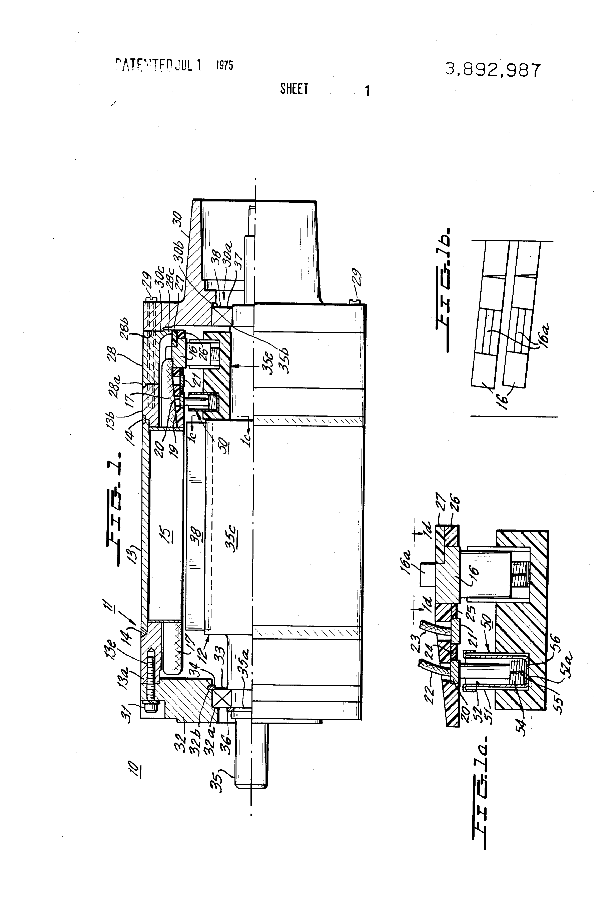
inside out motor design has a higher continuous rating FIG. 1 is a partial sectional view of a motor design in in contrast to conventional DC motors of the same size corporating the principles of the present invention; and weight. 1 a ra FIG. 1a shows an enlarged view of the commutation The problems of commutation in motors of the inside array in the motor of FIG. 1; out type has led to the development of a DC brushless FIG. 1b is a view of the commutator bar array looking type motor which employs electronic amplifiers and in the direction of arrows 1d-1d of FIG.1a; other solid state circuit elements to provide the neces FIG. Ic is a partial sectional view of the rotor perma sary commutation. The electronic amplifiers and cir nent magnet assembly of the motor shown in FIG. 1 cuit elements required for proper switching of power to 40 FIG.along taken the line 1c-1c of FIG. 1;
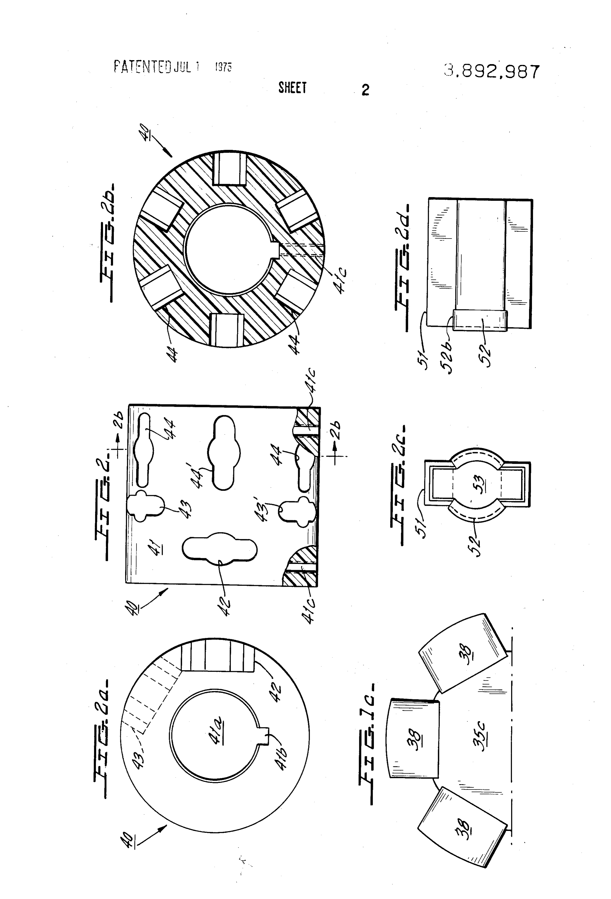
shows a top view of an alternative embodi the stator windings to generate the rotating field add ment of the rotor mounted brush ring actuator of FIG. significant cost and weight to the motor. The solid state 1;
switching circuitry also increases motor "cogging' FIG. 2a shows an end view of the brush ring actuator which occurs during low speed motor operation. of FIG. 2; t
BRIEF DESCRIPTION OF THE INVENTION FIG.2b shows a sectional view of the brush ring actu The numerous problems and disadvantages encoun ator of FIG. 2;
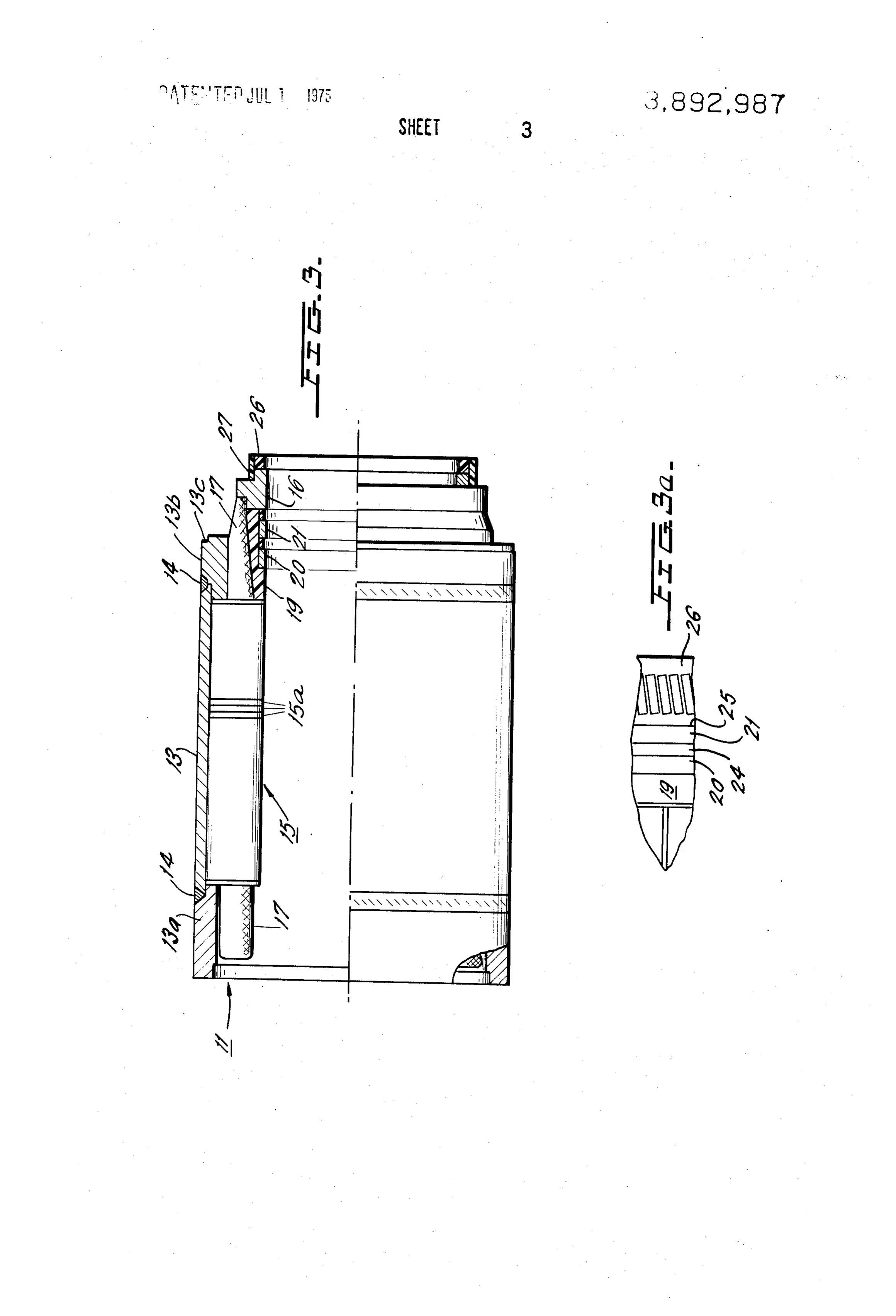
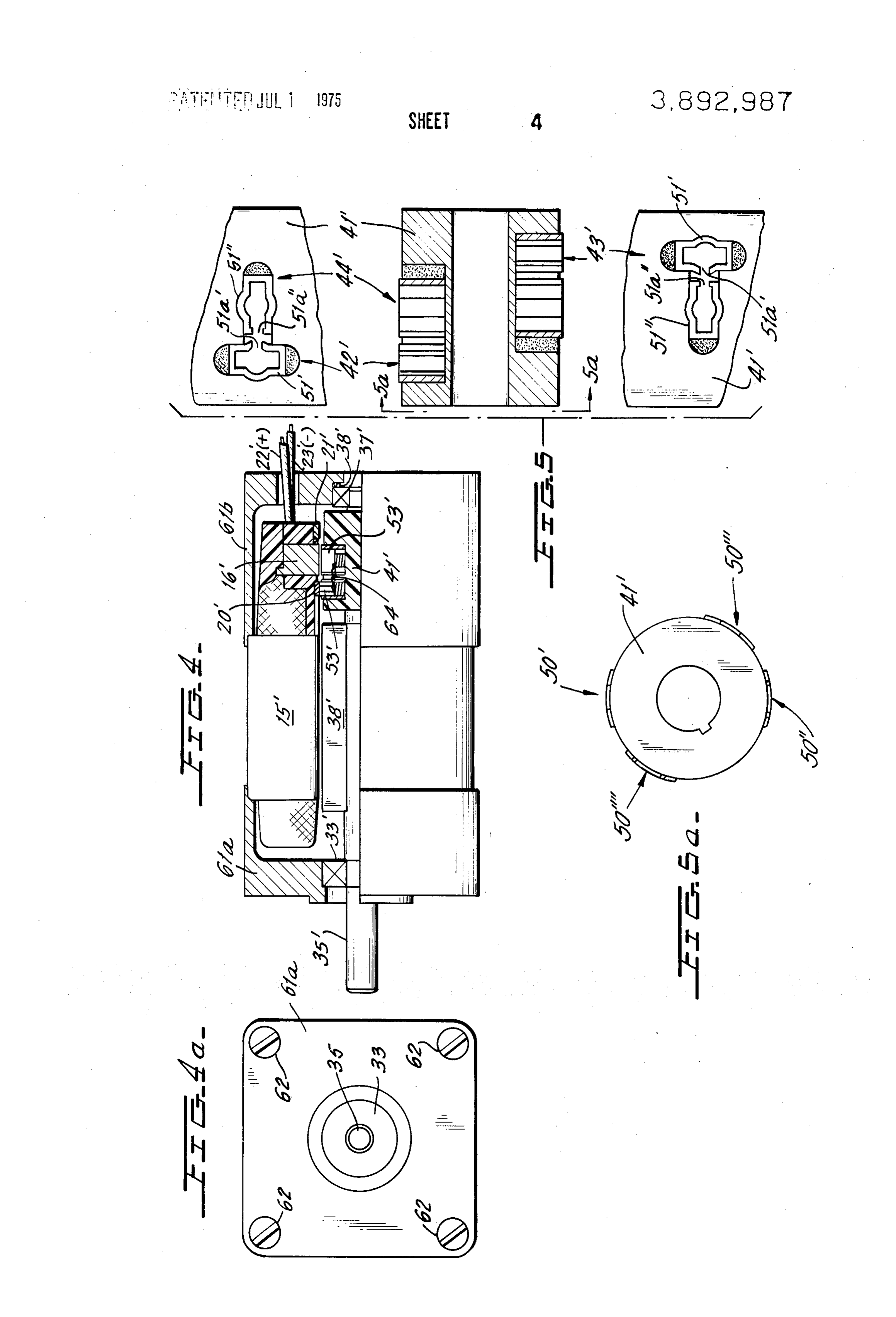
FIGS. 2c and 2d show enlarged end and side view re tered in DC motors of both the conventional and inside out design has led to the development of the present in spectively of the brush holders of FIG. 1; vention which is characterized by providing a method 50 assembly of FIG.an1;enlarged sectional view of the stator FIG. 3 shows of commutating the motor windings through the use of a novel electro mechanical switching arrangement in andFIG. 3a shows an enlarged view of the commutator ring assemblies of FIG. 3 looking in the direction which the stator assembly is provided with first and sec of arrows 3c-3c.; .' ond annular conductive rings and an array of commuta FIG. 4 is a side view, partially sectionalized, of an tor bars. The rotor assembly is provided with the first 55 other embodiment of the present invention; and second arrays of ring brushes which revolve with FIG. 4a shows an end view of the machine of FIG. 4; the rotation of the rotor shaft and engage, respectively, FIG. 5 shows a sectional view of the rotor brush ring the first and second conductive rings. The ring brushes assembly of FIG. 4; and are each electrically connected to associated commuta 60 FIG. 5a shows an end view of the brush ring assembly tor brushes which in turn wipingly engage the stator of FIG. 4.
mounted commutator bars to simultaneously couple DETAILED DESCRIPTION OF THE INVENTION the opposite terminals of each of the stator coils to the opposite polarities of the DC source so as to progres One embodiment 10 of the DC motor embodying the sively energize the stator coils whose magnetic fields 65 novel commutation technique is depicted in FIGS. interact with the rotating magnetic fields of the rotor 1-3a and is comprised of a stator assembly 11 and a co permanent magnets to effect and sustain rotation of the operating rotor assembly, 12. The stator comprises a rotor shaft. first elongated hollow cylindrical housing portion 13 7 having its opposite ends welded to relatively short ring rotor shaft by means of its central opening 41a which shaped housing members 13a and 13b the weldments has a keyway 41b for receiving a pair of fasteners (not being shown at 14. The stator has a laminated stator shown) which threadedly engage radially aligned core 15 having individual laminations which are prefer tapped openings 41c to lock drum 41 to shaft portion ably stamped from plates for suitable magnetic mate 5 35e.
rial. The actuator drum is formed of an insulating material The group of laminations forming stator core 15 have and is provided with a plurality of brush assembly open multi-turn coils wound thereon. Numeral 17 designates ings 42-44 cach adapted to receive a brush assembly. the stator winding shown in FIGS. 1 and 3 in simplified In the preferred embodiment there are three openings fashion. Diametrically opposed coils are electrically O 42; three openings 43, and six openings 44. The open connected to one another so as to be coupled in electri ings 42 receive brush assemblies whose brushes wip cal series. The remaining electrical terminal of each ingly engage conductive ring 20. In a like manner, the coil is connected to an associated commutator bar 16. brushes mounted in openings 43 wipingly engage con The commutator bars 16 are arranged in an annular ductive ring 21 and the brushes mounted in openings array in an equispaced manner and are adapted to be 44 wipingly engage the commutator bars 16. physically engaged by associated commutator brushes FIGS. 1 and 2c show a brush assembly 50 comprising as will be described in greater detail below. a brush holder 51 containing a U-shaped clamp 52. The Annular shaped insulating member 19 secures con free ends 52b are bent downwardly about holder 51 ductive rings 20 and 21 which are cylindrically shaped (FIG. 2d). The brush 53 is slidably mounted within conductive members, each being electrically con holder 51 and the central portion of brush 53 slidably nected to one polarity of a DC source through insulated engages clamp 52 (FIG. 2c). A helical spring 54 rests wires 22 and 23, respectively. A pair of ring shaped in on the base 52a of clamp 52 and urges brush 53 toward sulators 24 and 25 serve to electrically insulate the engagement with conductive ring 20. A conductor 55 rings 20 and 21 and the bars 16 from one another. The is electrically connected to the bottom of brush 53 and outwardly extending projections 16a of commutator has its opposite end electrically connected to a contact bars 16 (FIG. lb) serve to facilitate electrical connec button 56. Each remaining brush assembly is similar in tion between the bars 16 and the coils of winding 17. design and function to the assembly 50 described here Insulator rings 26 and 27 secure commutator bars 16 inabove.
and further serve to electrically insulate bars 16 from The brush assemblies mounted in openings 42 are the conductive cylindrical housing portion 28 whose 30 each electrically connected to associated brush assem projecting rim 28a is received by a notch 13c in housing blies in certain of the openings 44. Likewise, the assem member 13b. blies mounted in openings 43 are electrically con Spacer member 28 is provided with a plurality of nected to associated brush assemblies in the remaining smooth bores (see 28b-FIG. 1) which are aligned with openings 44. For example, as shown in FIG. 2, the a like number of tapped holes (see 13e-FIG. 1) for re brush in opening 42 is electrically connected to the ceiving fasteners 29 which serve to secure end plate 30 brush in opening 44' while the brushes in openings 43 and spacer 28 to stator housing member 13b. The and 43' are electrically connected to the brushes in shoulder 28b of spacer 28 likewise interfits with the openings 44 and 44'. The actual electrical connections complementary shaped mating surface 30c of end plate 40 are omitted for purposes of simplicity. 30. The inwardly directed end portion 28c receives the As shown in FIG. 1b, the commutator bars 16 are off insulator ring 27. In a like manner stator housing mem set at an angle relative to the longitudinal axis of the ber 13a is provided with a plurality of tapped openings motor and hence are likewise offset relative to the com (see 13e-FIG. 1) which receive threaded fasteners 31 mutator brushes placed in openings 44 which cause a to secure end plate 32 to stator housing member 13a. 45 "make-before-break' contact action between the com End plate 32 has an annular shaped seat 32a for shaft mutator brushes and commutator bars. bearing 33 which is secured to end plate 32 by a retain Operation of the motor of FIGS. 1-2d is as follows. ing ring 34 which is seated in an annular groove 32b. An electrical path extends from one terminal of the DC The rotor shaft 35 is restrained from experiencing any source, through lead 22, to conductive ring 20. The linear movement by means of retaining ring 36 which brushes (three, in preferred embodiment) in openings bears against a marginal edge of bearing 33 and is 42 continuously wipingly engage conductive ring 20 re seated in groove 35a provided in shaft 35. gardless of the angular orientation of the rotor assem End plate 30 has a central opening 30a through bly. The other terminal of the DC source is electrically which rotor shaft 35 protrudes. An annular seat 30b in connected to conductive ring 21 through lead 23 and plate 30 receives bearing 37. An annular shaped spring through the brushes in openings 43 which wipingly en washer 38 having an S-shaped cross section serves to gage ring 21. The brush in opening 42 thereby couples provide a cushioned mounting for the rotor assembly. one terminal of the DC source to the brush in opening The shoulder 35b on shaft 35 rests against the inner 44' while the brush in the opening 43 couples the other marginal edge of bearing 37. terminal of the DC source to the brush in opening 44. The rotor assembly 12 is comprised of rotatable shaft 60 There are six brushes in the six openings 44. Three 35 which is fitted within the hollow interior of the sta of the brushes are coupled to "+" while the remaining tor assembly. The central portion 35c of the rotor shaft three are coupled to "-". Each + brush is paired with is of enlarged diameter relative to the ends and is pro a diametrically opposed - brush to couple DC power vided with axially aligned grooves for receiving a plu across a pair of diametrically opposed commutator bars rality of elongated permanent magnet members 38 65 16 thereby energizing a pair of series connected dia bonded into position (FIG. 1c). metrically opposed coils of the stator winding 17. The A brush ring assembly 40 comprising a drum 41 stator coils cooperate with the stator laminated core to (FIGS. 1 and 2-2d) is mounted upon portion 35e of the generate a magnetic field which interacts with mag 8 netic fields created by the permanent magnet members 20', and 21'. The openings 42" communicate with se of the rotor assembly to cause rotation of the rotor. The lected ones of the openings 44 to form “T-shaped' six brushes in openings 44 then progressively move into openings. Likewise openings 43' communicate with the wiping engagement with the next three pairs of commu remaining openings 44' to similarly form T-shaped tator bars to sustain rotor rotation. 5 openings. The brush holders 51' are severed at 51a" to In the embodiment shown in FIGS. 1-2d, the motor communicate with the severed portion 51a' in brush is of six pole design utilizing six permanent magnets 38 holder 51'. This arrangement provides a direct chan in the rotor assembly and three pairs of--and-brushes nel for a conductor 64 (see FIG. 4) to be directly con in openings 44. It should be understood, however, that nected between brushes 53' (FIG. 4). The rounded a greater or lesser number of poles may be utilized in O ends of the openings are filled with an epoxy after the the motor, depending upon the needs of the user. The holders are inserted. In all other respects the brush as six pole motor disclosed herein has been found to pro semblies of FIGS. 4-5a are the same. As shown in FIG. vide smooth operation at slow speeds. 4, the stator conductive rings 20' and 21' are posi It is generally accepted that energizing windings uti tioned on opposite sides of the commutator bars 16'. lizing the DC brushless concept requires relatively The embodiment of FIGS. 4-5a is a four-pole motor. large numbers of solid state components in an elec There are two pairs of commutator brushes (50'-50' tronic control circuit in order to develop the large num and 50'-50'; see FIG. 5a). However, the operation ber of commutator bar segments which are necessary is the same as that described for the: embodiment of for smooth operation at slow speeds. In view of the FIGS 1-3a. • foregoing, another application of the present invention The invention disclosed and claimed herein is not would be to use the switching techniques described limited to the specific mechanisms and techniques herein to effect smooth motor operation at slow speeds, herein shown and described since modifications will and then switch to a static control incorporating a undoubtedly occur to those skilled in the art. Hence, smaller number of solid state circuit elements to ener departures may be made from the form of the instant gize the windings during high speed operation. Such an invention without departing from the principles arrangement would serve to provide a smooth operat thereof.
ing motor at slow speeds and to provide the long life What is claimed is:
operation of the DC brushless control circuit for high 1. Switching apparatus for a machine responsive to a speed conditions. source of DC power and having interacting rotor and The novel DC motor described herein, in contrast to stator assemblies which rotate relative to each other, conventional DC motors, permits the use of a rotor as the rotor having at least a two-pole permanent magnet sembly having a relatively small mass and a corre structure for creating a magnetic field and the stator sponding low moment of inertia. Moreover, the perma having a winding with a plurality of energizeable coils nent magnet members may be of the ceramic type to 3 5 arranged at spaced intervals around the stator, said further reduce the mass of the rotor assembly. Effect coils having an array of commutator bars associated ing commutator switching in the stator assembly per therewith for supplying electrical power thereto for mits the use of a larger copper volume which signifi progressively creating magnetic fields in said stator cantly reduces the amount of heating occurring in the which interact with those in said rotor, said apparatus electrically energized stator assembly, which serves to comprising:
prolong the useful operating life of the motor. Also, 40 a first and second spaced conductive rings associ having the windings in the stator eliminates the stress ated with said stator, said conductive rings being normally experienced by the rotor-mounted windings, positioned proximate said commutator bars; thereby prolonging the life of the windings and the mo b. means for respectively coupling each of said con tor. ductive rings to opposite polarities of said DC FIGS. 4-5a show another embodiment of the present Source; and invention which employs the commutation techniques c. first and second actuating means associated with previously described and wherein like elements are said rotor, said first and second actuating means designated by like but primed numerals. Exemplary being adapted to progressively and sequentially embodiment 60 is comprised of housing members 6 la electrically couple said first and said conductive and 61b, shown partially sectionalized for purposes of 50 rings to the commutator bars during the relative ro simplicity. The housing end portions have circular tation so as to momentarily and progressively cou shaped openings for receiving the stator assembly ple each coil to both polarities of said source and winding. However, the end portions have square to couple each subsequent coil across said source shaped exteriors which are each provided with aligned 55 before the preceding coil is decoupled from said elongated openings in their corners to receive fasteners SOC.
62 (FIG. 4a) to secure end portions 61a and 61b to one 2. The switching apparatus of claim 1 wherein said another and thereby secure the stator assembly there first and second conductive rings are disposed on one between. The right-hand end of housing portion 61b is side of said array of commutator bars. provided with a bearing 37' for mounting rotor shaft 60 3. The Switching apparatus of claim 1 wherein said 35 having secured thereto an array of permanent mag first and second conductive rings are disposed on oppo nets 38'. A brush ring actuator 41' formed of a suitable site sides of said array of commutator bars. insulating material is rigidly secured to shaft 35' in a 4. The switching apparatus of claim 1 wherein said suitable manner. first and second actuating means each comprises first A plurality of brush assemblies 50' are secured in 65 and second electrically connected brush assemblies ro openings 42'-44 in drum 41' in a suitable manner and tatable with said rotor assembly for respectively wip the brushes are biased radially outwardly so as to wip ingly engaging one of said conductive rings and said ingly engage commutator bars 66, and conductive rings commutator bars.
Page 9scan →
5. Switching apparatus for a machine responsive to a relative rotation so as to momentarily and progres source of DC power and having interacting rotor and sively couple each coil to both polarities of said stator assemblies which rotate relative to each other, Source and to couple each subsequent coil across the rotor having at least a two-pole permanent magnet said source before the preceding coil is decoupled structure for creating a magnetic field and the stator 5 from said source.
having a winding with a plurality of energizeable coils 6. The apparatus of claim 5 wherein said first and arranged at spaced intervals around the stator, said second actuating means each comprises first and sec coils having an array of commutator bars associated ond brush assemblies for respectively wipingly engag therewith for supplying electrical power thereto for ing said first and second conductive rings and said com progressively creating magnetic fields in said stator O mutator bars.
which interact with those in said rotor, said apparatus 7. The apparatus of claim 6 wherein said first and comprising: second brush assemblies are angularly displaced from a first and second spaced conductive rings associ one another about said drum means so as to simulta lated with said stator, said conductive rings being neously engage commutator bars associated with the positioned proximate said commutator bars; 15 same coil.
b: means for respectively coupling each of said con 8. The apparatus of claim 5 wherein said drum means ductive rings to opposite polarities of said DC comprises a cylindrical shaped insulating member hav source; and ing openings for receiving said brush assemblies and c. drum means associated with said rotor and adapted wherein each brush assembly comprises a brush mem to rotate there with, said drum means having first ber slidably mounted in one of said drum openings and and second actuating means mounted thereon, said spring biased radially outward.
first and second actuating means each comprising 9. The apparatus of claim 1 wherein the longitudinal brush assemblies adapted to progressively and se axes of said commutator bars are offset at an angle rela quentially electrically couple said first and second tive to the rotating axis of said rotor shaft. conductive rings to the commutator bars during the * : *k : *k
Provenance
- Collection
- Patents citing this work
- Pages
- 9
- Method
- pdftotext (the PDF's own text layer) + pdftoppm 300dpi page scans
- Patent office record
- patents.google.com →
- Source
- Google Patents citing-documents table
- Assignee
- Kollmorgen Corp
- Published
- 1975-07-01
- Transcribed from
- patentimages.storage.googleapis.com →