

patent · US4280482A
Method and apparatus for collecting, intensifying and storing solar energy
28 July 1981
Text
Page 1bibliographic recordscan →
United States Patent (19)
Nilsson, Sr.
54 METHOD AND APPARATUS FOR
COLLECTING, INTENSIFYING AND
STORING SOLAR ENERGY
75 Inventor: Jack E. Nilsson, Sr., Easley, S.C.
73 Assignee: Seige Corporation, Greenville, S.C.
int. Cl.................................................. F24J 3/02 52 U.S. C. .................................... 126/430; 126/436;
290,851 12/1883 Calner .................................. 126/438 1,599,481 9/1926 Marcuse ............................... 126/438
1,951,403 3/1934 Goddard .............................. 126/440 4,010,732 3/1977 Sawata et al. ... 60/64 X 4,043,315 8/1977 Cooper ................................. 126/440 4,056,093 l 1/1977 Barger .................................. 126/440 4,081,024 3/1978 Rush et al.... 126/436 X
4,106,479 8/1978 Rogers ................................. 26/439
FOREIGN PATENT DOCUMENTS
472427 12/1950 Italy ......................................... 126/438 Primary Examiner-Larry Jones
Attorney, Agent, or Firm-Bailey, Dority & Flint
A method and apparatus for collecting, intensifying and storing solar energy which includes a hollow spherical vessel having a polished reflective interior surface. A window is provided in the wall of the vessel for allow ing concentrated rays from the sun to enter into the interior of the vessel and be absorbed by a solar collec tor. The collector includes a substantially black (or a selective coating) heat absorbing surface carried by a spherical member which is centrally located within the spherical vessel. Heat absorbing media such as metal shots, are carried within the spherical member and change from a solid state to a liquid state as it absorbs the solar energy. The heat absorbing media cause radi ant energy to be radiated radially in a symmetric beam pattern to the reflective vessel wall where the radiation is reflected back to the spherical member. The reflected radiant energy in conjunction with the sun's rays inten sify the temperature of the heat absorbing media pro ducing a thernal power supply.
9 Claims, 4 Drawing Figures
Drawings
Page 2drawing sheetscan →
Page 3drawing sheetscan →
Page 4scan →
the spherical container intensifying the temperature of
METHOD AND APPARATUS FOR COLLECTING, the heat absorbing means.
INTENSIFYING AND STORING SOLAR ENERGY Normally, the heat absorbing means begins in a solid state and as the intensity of the temperature supplied by
BACKGROUND OF THE INVENTION the rays from the sun and the reflected radiant energy The present invention relates to a method and appara increases, a result of it is changed from a solid to a liquid state. As the radiant energy being reflected back and tus for storing solar energy and more particularly to a forth between the exterior wall of the spherical con method and apparatus for collecting, intensifying and tainer and the interior wall of the vessel, the spherical storing solar energy for subsequent use. Heretofore, 10 container with the heat absorbing means therein is energy as a source of power has normally been col raised to very high temperatures. Transfer tubes are lected by solar collector panels mounted on structures carried within the spherical container through which a in open space through which fluid such as air or liquid heat transferring fluid passes for removing heat from passes for transferring the collected thermal heat to a storage chamber for subsequent use. These storage beds 15 the molten heat absorbing means for use as a source of thermal power. A vacuum is provided in the space may take many different configurations and one particu between the external wall of the spherical container and lar configuration utilized are rock beds that are posi the interior wall of the spherical vessel. A vacuum is tioned below the building. One problem with rock beds also provided in the interior of the spherical container. is that they are not a very efficient means of storing high Accordingly, it is an important object of the present temperatures. While these storage chambers heretofore 20 invention to provide a method and apparatus of produc utilized may be satisfactory for heating buildings and ing a high intensity source of thermal power from solar the like, they would not be satisfactory for operating energy.
power plants. Another important object of the present invention is In U.S. Pat. No. 4,056,093 there is disclosed a solar to provide an apparatus for collecting, intensifying and heating unit which includes a double wall boiler having 25 storing solar energy which is clean and extremely sim a pair of spaced inner and outer hemispherical walls ple in operation.
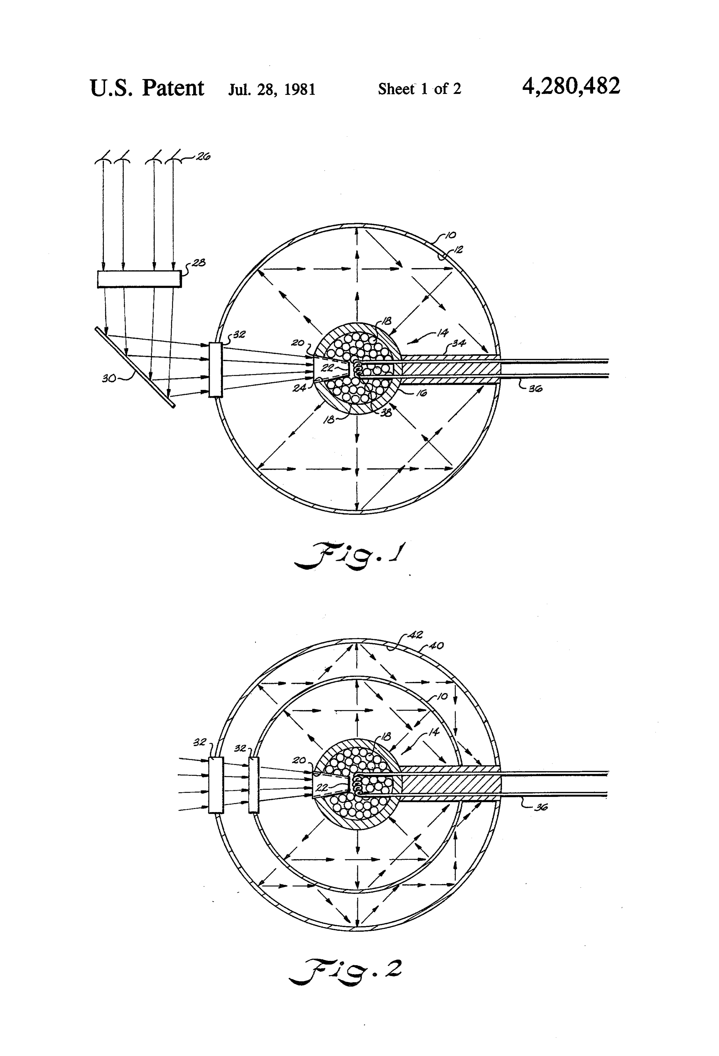
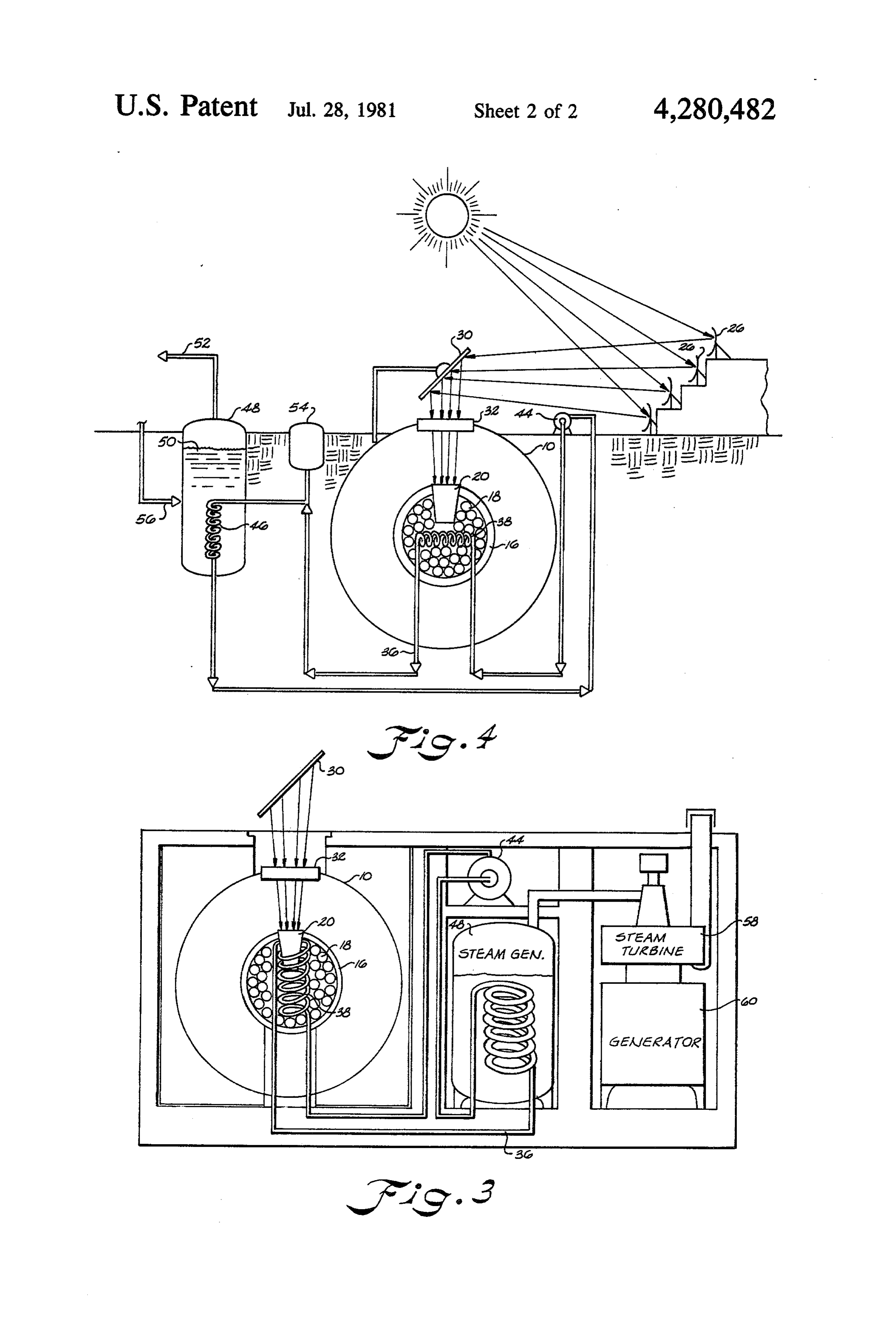
defining a closed chamber therebetween in which liquid Still another important object of the present inven that is to be heated is carried. Solar energy passes tion is to provide a power source which utilizes solar through a lens system for heating the liquid. energy in combination with reflected radiant energy to In U.S. Pat. No. 4,043,315 there is disclosed an omni 30 produce a high intensity thermal supply. directional solar heater collector having a transparent, These and other objects and advantages of the inven spherical outer shell. A spherical inner shell is carried tion will become apparent upon reference to the follow within the outer shell and contains a plurality of light ing specification, attendant claims and drawings. magnifying lens spaced along the periphery thereof. A plurality of heat collecting elements is carried within 35 BRIEF DESCRIPTION OF THE DRAWINGS the inner shell spaced from the magnifying lens so that FIG. 1 is a sectional view of a solar power source maximum light and heat intensity focuses upon these constructed in accordance with the present invention, elements. - FIG. 2 is a sectional view of a modified form of the In U.S. Pat. Nos. 1,169,839; 1,661,473; and 1,599,481 invention, there are disclosed other solar heaters and accumulators 40 FIG. 3 is a schematic illustration showing a solar cell in which a liquid is heated by the rays of the sun utiliz constructed in accordance with the present invention ing lens systems and reflecting mirrors. being utilized for heating hot water and/or steam for One problem with the majority of the solar heaters residential or industrial use, and heretofore utilized, is that they do not generate and FIG. 4 is a schematic illustration showing a solar cell store temperatures of sufficient intensity for operation 45 constructed in accordance with the present invention of power plants and the like during periods of time of being utilized in an industrial application such as a darkness or during inclement weather when clouds and major power generation plant.
the like reduce the solar rays received by the collector. DESCRIPTION OF A PREFERRED
Embodiment
A method and apparatus for collecting, intensifying Referring in more detail to the drawings, there is and storing thermal energy which includes a hollow illustrated in FIG. 1 a solar power cell constructed in spherical vessel having an interior wall. A window is accordance with the present invention which includes a provided in the wall of the vessel for allowing concen hollow spherical vessel 10 constructed of any suitable trated rays from the sun to enter into the interior of the 55 material such as stainless steel that has a reflective pol vessel. A spherical container is centrally located within ished coating 12 provided on an interior wall thereon. the vessel and has a solar collector carried thereon. The This coating can be any suitable highly reflective sur solar collector in one particular embodiment is coni face such as polished stainless steel or a mirror surface. cally shaped and has a substantially black (or selective Carried within the spherical vessel iO is solar collec coating) surface thereon for receiving and absorbing the 60 tor generally designated by the reference character 14, rays passing through the window of the spherical ves that will be referred to hereinafter as an emitter. The sel. Heat absorbing means in one particular embodiment emitter includes a spherical member 16 that is filled in the form of metal shots is carried in the spherical with heat absorbing material 18. Adjacent one side of container for absorbing and storing the thermal energy the spherical member 16 and extending into the interior collected by the solar collector causing radiant energy 65 thereof is a conical shaped member 20 (or other desir to be emitted from the spherical container. A polished able geometric shape) that has a closed bottom 22 adja reflective surface is carried on the interior wall of the cent the small diameter end thereof and an open end spherical vessel for reflecting the radiant energy back to adjacent the large diameter end thereof. The interior 5 wall 24 of the conical shaped member is coated with a losses to the outside and it also tends to naturally focus substantially black (or selective surface) heat absorbing reflective patterns of radiant heat to the center thereof surface 24 which is provided for receiving and absorb for striking the emitter surface. ing thermal energy. There are many suitable surface coatings 12 that can The rays from the sun are directed by converging be utilized having satisfactory reflecting properties and mirrors 26 through an iris assembly 28 which can be in one particular embodiment a silver coating is utilized. opened and closed for controlling the flow of rays However, it is to be understood that other coatings such therethrough. A secondary mirror 30 reflects the con as aluminum, gold, copper, rodium and platinum reflec centrated rays of sunlight through an optical window 32 tive coatings could also be utilized. Silicon monoxide provided in the wall 10 of the spherical vessel. As the 10 coated over the silver will protect the reflective surface rays enter into the spherical vessel 10 they strike the from the severe thermal environment encountered black solar collecting surface 24 carried on the interior within the spherical vessel 10. To minimize heat losses, of the conical shaped member which absorbs the ther mal energy therefrom. This thermal energy is then the ing exterior of the vessel is polished or coated produc a reflective surface.
transferred by means of conduction to the heat absorb 15 In one ing material 18 carried within the spherical container interior ofparticular the conical embodiment, the coating on the member 20 is carbon, however, 16. The heat absorbing material may be in the form of other suitable low emissivity type material such as pyro metal shots which would become molten when the lytic graphite can be utilized for absorbing thermal system is operational. Material such as aluminum, cop energy.
per, brass bronze and other suitable metals would pro 20 The fluid heat transfer media that flows vide good stability, be non-stratifying and possess good through the tubes 36 and the coil 38 may also be any latent heat content characteristics. suitable material such as Dowtherm, Therminol, liquid The spherical container 16 has a low emissivity value sodium, carbon dioxide, high pressure water, etc. In order to increase the efficiency of storing thermal and is placed in or near the center of the interior of the energy spherical vessel and it is supported on a post 34. This 25 in the solar cell, the spherical vessel 10 can be post assembly 34 has passages extending therethrough concentrically located within another spherical vessel through which tubes 36 extend from outside of the 40. The interior wall 42 of the spherical vessel 40 has a spherical vessel 10 to the interior of the spherical con reflective coating similar to the reflective coating 12 tainer 16 providing communication with a coil or other provided on the interior wall of the spherical vessel 10 transfer tube configurations 38 that are carried within 30 for reflecting the radiant energy back towards the emit the container. Fluid flows through the tubes 36 and the ter 14 as shown by the broken lines and arrows. A vac transfer tubes 38 for transferring the stored thermal uum is also provided between the external surface of the energy collected by the heat absorbing media 18 exter vessel 10 and the interior surface of the spherical vessel nally of the spherical vessel 10. The post 34 can be 40. Like reference numerals are used for the same and constructed of any suitable material that is a poor con 35 similar elements. Multiple spherical vessels may also be utilized.
ductor of heat so as to minimize the loss of thermal energy from the emitter outside of the spherical vessel. In FIG. 4, the solar cell is illustrated as being utilized One suitable material is marionite. for heating water or generating steam in a tank for home In operation, the rays of the sun are focused by the consumption and industrial use. The solar cell can be mirror system through the optical window 32 to the 40 relatively small when being used for heating water. substantially black collective surface 24 of the conical The heat transfer media is pumped through the tubes member 20. The metallic heat absorbing material 18 36 by means of a pump 44. As the fulid passes through absorbs thermal energy from the conical shaped mem the coils 38 it absorbs thermal energy from the molten ber 20. As it absorbs the thermal energy it radiates radi metal 18 and is conveyed through tubes to a coil 46 ant energy radially outwardly therefrom as shown by 45 provided in a steam generating tank 48. As the heat the broken arrows. This radiant energy is reflected back transfer media is fed through the coil 46 it causes water by the mirror surface 12 carried on the interior of the 50 carried therein to boil to generate steam that is ex spherical vessel. As a result of the reflected radiant hausted out pipe 52. The heat transfer media is carried energy and the incoming solar energy passing through within a closed tubular system extending between the the window 32, the two sources of energy work in 50 pump 44 and the tank 48. A reservoir 54 is provided for unison intensifying the temperature of the heat absorb supplying the heat transfer media to the tubes 36. ing material 18 producing an intense source of thermal Makeup water is supplied through tube 56 to the steam energy. In order to minimize heat losses, a vacuum is generating tank 48.
provided in the space between the emitter 14 and the In FIG. 4, the solar cell is shown in an industrial interior wall of the spherical vessel 10. The interior of 55 application wherein the heat transfer media is fed the emitter is also evacuated of air. through the tubes 36 to a steam generating tank 48. The Any suitable optical system can be utilized for con output of the steam generating tank is, in turn, fed di centrating the rays of sun and focusing them on the rectly to a steam turbine 58 which drives a generator 60 collective surface 20. It has been found that parabolic for generating electrical power. Of course, it is to be mirrors can be positioned for concentrating the sun's 60 understood that the solar cell could be utilized in many rays and directing them through the iris assembly. The different industrial applications and the application purpose of the iris assembly is to regulate the amount of shown in FIGS. 3 and 4 are examples of such use. The concentrated rays that are supplied to the interior of the entire assembly such as illustrated in FIG. 4 can be spherical vessel. located underground so as to minimize thermal losses, The spherical vessel as previously mentioned, may be 65 or it can be carried within a concrete housing as illus constructed of any suitable material such as stainless trated in FIG. 3.
steel, and as a result of being spherical in shape there is Energy can be removed from the molten metal 18 in a high volume to surface ratio which minimizes heat other forms than thermal. For example, a thermocouple 6 or thermonic generator can convert thermal energy to a solar collector carried adjacent the center of said electrical energy for removal. spherical vessel spaced from the interior walls of While a preferred embodiment of the invention has said spherical vessel, said solar collector including; been described using specific terms, such description is (i) a container, for illustrative purposes only, and it is to be understood (ii) a substantially black heat absorbing surface that changes and variations may be made without de carried by said container for being contacted by parting from the spirit or scope of the following claims. said rays passing through said window, What is claimed is: (iii) heat absorbing means carried in said container 1. An apparatus for collecting, intensifying and stor 10 for absorbing and storing thermal energy from ing solar energy comprising: said heat absorbing surface and for heating said a hollow spherical vessel having an interior wall; container causing radiant energy to be emitted a window provided in said wall of said vessel for from said container, and allowing concentrated rays from the sun to enter (iv) said heat absorbing means being metal that into the interior of said vessel; goes from a solid state to a liquid state upon a solar collector centrally carried in said spherical 15 absorbing thermal energy from said substantially vessel, said solar collector having; black heat absorbing surface, (i) a spherically shaped wall, a polished reflective surface carried on an interior (ii) a substantially black collector surface for ab wall of said spherical vessel for reflecting radiant sorbing thermal energy from said concentrated 20 energy back to said container intensifying the tem rays, and perature of said heat absorbing means. (iii) a heat absorbing means carried in said con prising: 6. The apparatus as set forth in claim 5 further com tainer for absorbing and storing thermal energy said container is a spherical member which is cen from said collector surface, and for causing radi ant energy to be emitted, said heat absorbing 25 7. trally The carried within said hollow vessel.
apparatus as set forth in claim 6 further com means being a material which goes from a solid prising:
state to a liquid state upon absorbing thermal a conical shaped member having a large diameter end energy from said heat collector surface, and a small diameter end extending into said spheri a polished reflective surface carried on an interior cal member;
wall of said spherical vessel for reflecting said radi 30 a bottom carried on said small diameter end of said ant energy emitted by said heat absorbing means conical shaped member;
back to said spherically shaped wall of said solar said large diameter end of said conical shaped mem collector. ber facing said window so that said rays from the 2. The apparatus as set forth in claim 1 further com sun enter said conical shaped member; and prising: 35 said substantially black heat absorbing surface being a conical shaped member having a large diameter end carried on interior walls of said conical shaped and a small diameter end extending into said solar member.
collector through said spherically shaped wall; 8. The apparatus as set forth in claim 5 further com a bottom carried on said small diameter end of said prising:
conical shaped member; 40 said hollow vessel and said container being sealed; said large diameter end of said conical shaped mem and ber facing said window so that said rays from said a substantial vacuum provided in the space between sun enter said conical shaped member; and said container and said interior wall of said hollow a substantially black heat absorbing surface being vessel.
carried on an inner surface of said conical shaped 45 9. A method of collecting, intensifying and storing member. solar energy comprising:
3. The apparatus as set forth in claim 1 further com concentrating and directing rays from the sun prising: through a window of a sealed spherical vessel; said spherical vessel and said spherically shaped wall absorbing thermal energy from said rays with a col of said collector being sealed; and 50 lector;
a substantial vacuum provided in the space between accumulating and storing said thermal energy ab said solar collector and said interior wall of said sorbed by said collector with a heat absorbing spherical vessel. member centrally located in said spherical vessel 4. The apparatus as set forth in claim 1 further com causing said heat absorbing member to emit radiant prising: 55 energy and causing said heat absorbing member to heat transfer means extending from outside of said change from a solid state to a liquid state as it ab spherically shaped vessel through said heat absorb sorbs thermal energy;
ing means for transferring thermal energy from reflecting said radiant energy emitted by said heat said heat absorbing means externally of said spheri absorbing member with a reflective surface carried cally shaped vessel. 60 on an interior wall of said spherical vessel back to 5. An apparatus for collecting, intensifying or sustain said heat absorbing member; and ing and storing solar energy comprising: externally removing thermal energy from said heat a hollow spherical vessel having an interior wall; absorbing member with a heat transfer means from a window provided in said wall of said vessel for said spherical vessel providing a source of thermal allowing concentrated rays from the sun to enter 65 power.
into the interior of said vessel;
Provenance
- Collection
- Patents citing this work
- Pages
- 6
- Method
- pdftotext (the PDF's own text layer) + pdftoppm 300dpi page scans
- Patent office record
- patents.google.com →
- Source
- Google Patents citing-documents table
- Assignee
- Seige Corporation
- Published
- 1981-07-28
- Transcribed from
- patentimages.storage.googleapis.com →