

patent · US4409963A
Solar optical energy collector
18 October 1983
Text
Page 1bibliographic recordscan →
as i ; v. iv.
United States Patent (19)
Mori
54). SOLAR OPTICAL ENERGY COLLECTOR
Inventor: Kei Mori, 3-16-3-501, Kaminoge,
Setagaya-ku, Tokyo, Japan
30 Foreign Application Priority Data
Jun. 27, 1980 (JP) Japan ................................ 55-087277 Jun. 27, 1980 JP Japan ...................... ... 55-087279 Int. Cl. ................................................. F24J 3/02 52 U.S. Cl. .................................... 126/440; 126/424;
1,683,266 9/1928 Shipman .............................. 126/440 3,493,291 2/1970 Webb .................................. 126/440 3,998,204 12/1976 Fuchs et al. ... 26/440 4,026,267 5/1977 Coleman ............................. 126/440 4,043,315 8/1977 Cooper ................................ 126/440 4,056,093 11/1977 Barger ................................. 126/440 4,057,048 11/1977 Maine .................................. 26/440
4,136,670 1/1979 Davis .................................. 126/440 4,205,661 6/1980 Chapman ..... ... 126/440 4,267,823 5/1981 Bohget al. ... ... 126/440 4,282,858 8/1981 Bowers ............................... 126/440 Primary Examiner-Daniel J. O'Connor
Attorney, Agent, or Firm-Merchant, Gould, Smith,
Edell, Welter & Schmidt
A solar optical energy collector having a lens system for concentrating sun beams and a sun beams receiving system for introducing said sun beams being concen trated into a optical-conductor cable.
In order to obtain the most effective arrangement of the lens system, said lens system comprises a plurality (N) of Fresnel lenses (1, 1...) each formed in the shape of a hexagon, i.e. N=3n(+1) Fresnel lenses (1, 1...) are disposed around one Fresnel lens (1) so that each side of the one Fresnel lens (1) positioned in the center of the lens system adjoins to one side of each respective sur rounding Fresnel lenses (1, 1. . . ) in a concentric-circu lar relationship, wherein (n) stands for a natural num ber.
4 Claims, 4 Drawing Figures
Drawings
Page 2drawing sheetscan →
Page 3drawing sheetscan →
Page 4drawing sheetscan →
Page 5drawing sheetscan →
Page 6scan →
The basic components of the solar optical energy
SOLAR OPTICAL ENERGY COLLECTOR collector include a Fresnel lens system for concentrat ing sun beams and a sun beam receiving system for
The present invention relates to an improvement of a introducing said sun beams being concentrated into an solar optical energy collector. More particularly, the 5 optical-conductor cable.
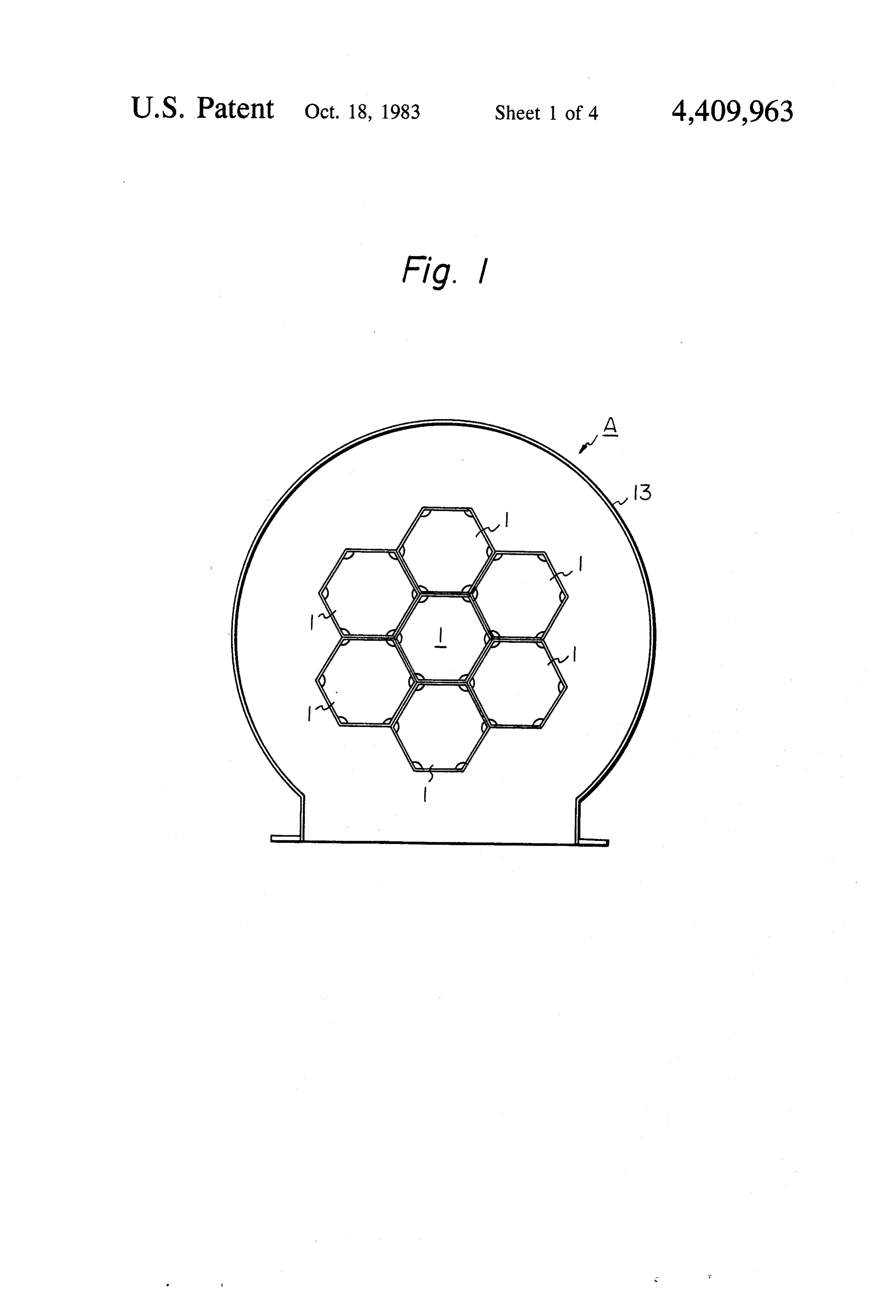
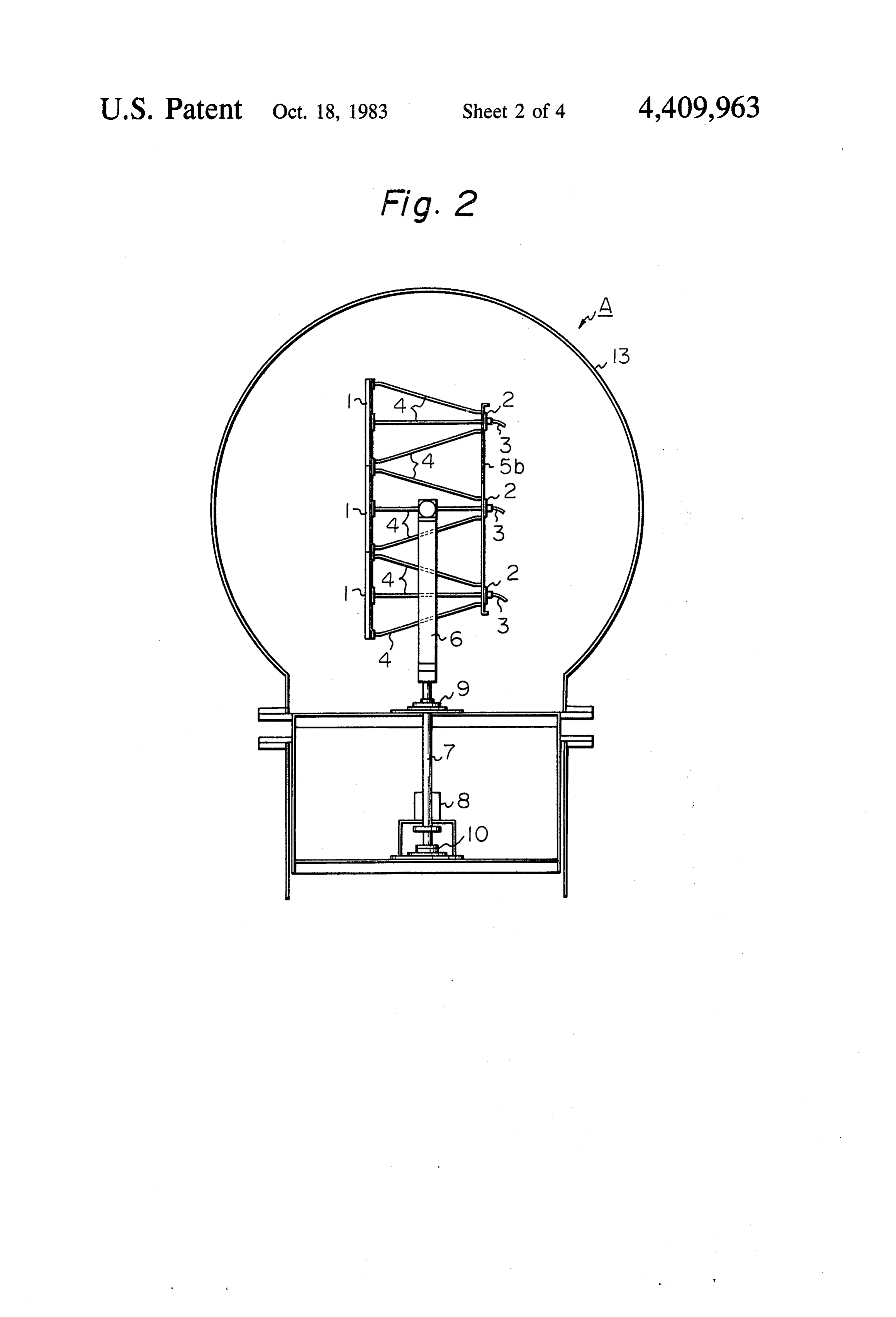
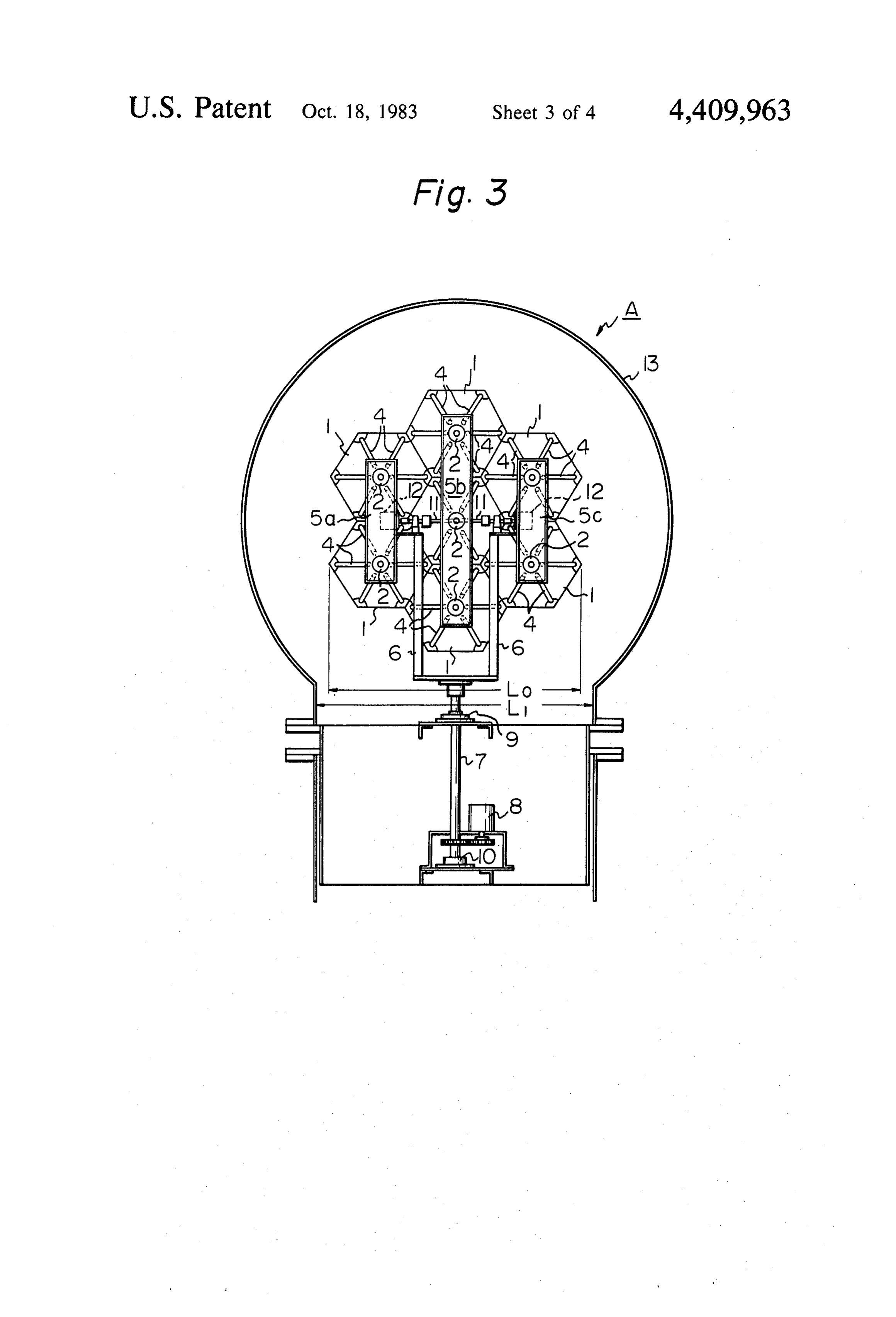
present invention relates to a novel arrangement of Referring to FIGS. 1 through 3, the reference nu Fresnel lenses which are mounted on the collector for meral 1 represents a Fresnel lens formed of a light trans collecting solar energy and which can collect Sunbeams parent material, such as plastic or glass, used to concen at the highest efficency and the most stable condition. trate sun beams. As shown in FIG. 1, a Fresnel lens 1 Recently, energetic developments and research have 10 formed in the shape of a hexagon placed in the center of been made in various fields for effective utilization of the capsule. A plurality of Fresnel lenses 1, 1 . . . , also solar energy with a view to meeting the requirement of formed in the shape of hexagons are disposed around saving energy. The present invention belongs to one of said one central Fresnel lens 1 so that each side of said the above developments and research utilizing the radi Fresnel lens 1 positioned in the center adjoins to one ative energy of the sun. 15 side of each of the respective surrounding Fresnel lenses Many attempts have heretofore been proposed to 1, 1 . . . . As a result, seven Fresnel lenses in all are obtain an optimum arrangement of Fresnel lenses utilized. The Fresnel lenses forming the lens system are mounted on a solar optical energy collector which can quite the same in their dimensions and are made with collect sun beams at the highest efficiency and at the same material. In the rearward side of each Fresnel lens most stable condition. However, such an optimum ar- 20 1 sun beam focusing members 2, 2 . . . forming the re rangement of Fresnel lenses was not achieved until the ceiving system are disposed at regular intervals from present. Furthermore, the construction of a solar opti the Fresnel lenses, respectively. Said sunbeam focusing cal energy collector is apt to become large. Therefore, member 2 are intended to focus sun beams which are in the prior techniques, it was quite difficult to prevent concentrated by means of the Fresnel lenses 1. the influence of the wind upon said collector and to 25 The Sun beams received by said sun beam focusing operate the collector smoothly and precisely to track members 2, 2 . . . are guided to a desired position (not the movement of the sun.
The invention as claimed is intended to overcome the shown in the drawings) through optical-conductor ca aforementioned defect of the prior techniques. It solves bles 3, 3. . . , and then they are directly used as illumi the problems, firstly, by providing a novel arrangement 30 nating rays or they are utilized after they have been of Fresnel lenses, each lens having the shape of a hexa converted to electric energy, thermal energy or the like. As shown in FIGS. 2 and 3, the Fresnel lenses 1 and gon, arranged in a concentric-circular relationship; se condly, by using a transparent spherical capsule which the sun beam focusing members 2 are integrally con hermetically includes Fresnel lenses; and thirdly, by nected with each other by connecting rods 4. Holding turnably mounting the Fresnel lenses around two axes 35 plates 5a, 5b and 5c are respectively provided to fix said perpendicularly intersecting with each other at the lens and receiving systems. Reference numerals 6, 7, 8, centroid of the Fresnel lenses. 9 and 10 respectively represent supporting arms, which The advantages offered by the present invention are are connected to the holding plates. 5a and 5c, a turnable that a plurality of Fresnel lenses can be disposed with vertical shaft, a vertical motor, a radial bearing and a thrust bearing. The above mentioned lens and receiving out gaps therebetween and can form a big circular sur- 40 systems face for sun beam concentrating as a whole, which are supported by the vertical shaft 7 through results in providing the most effective arrangement of the supporting arms 6, and can be turned around the the Fresnel lenses. In addition, the influence from the axis of the vertical shaft 7. Reference numerals 11 and wind can be prevented, and gyrating mass of the Fres 12 represent a turnable horizontal shaft and a horizontal nel lenses may be reduced to a minimum. Therefore, 45 motor, respectively. Said horizontal motor 12 is pro according to the present invention, the operation for vided on the holding plate 5a and or 5c so as to turn the tracking the movement of the sun can be performed lens and receiving systems around the axis of the hori very quickly and smoothly. zontal shaft 11.
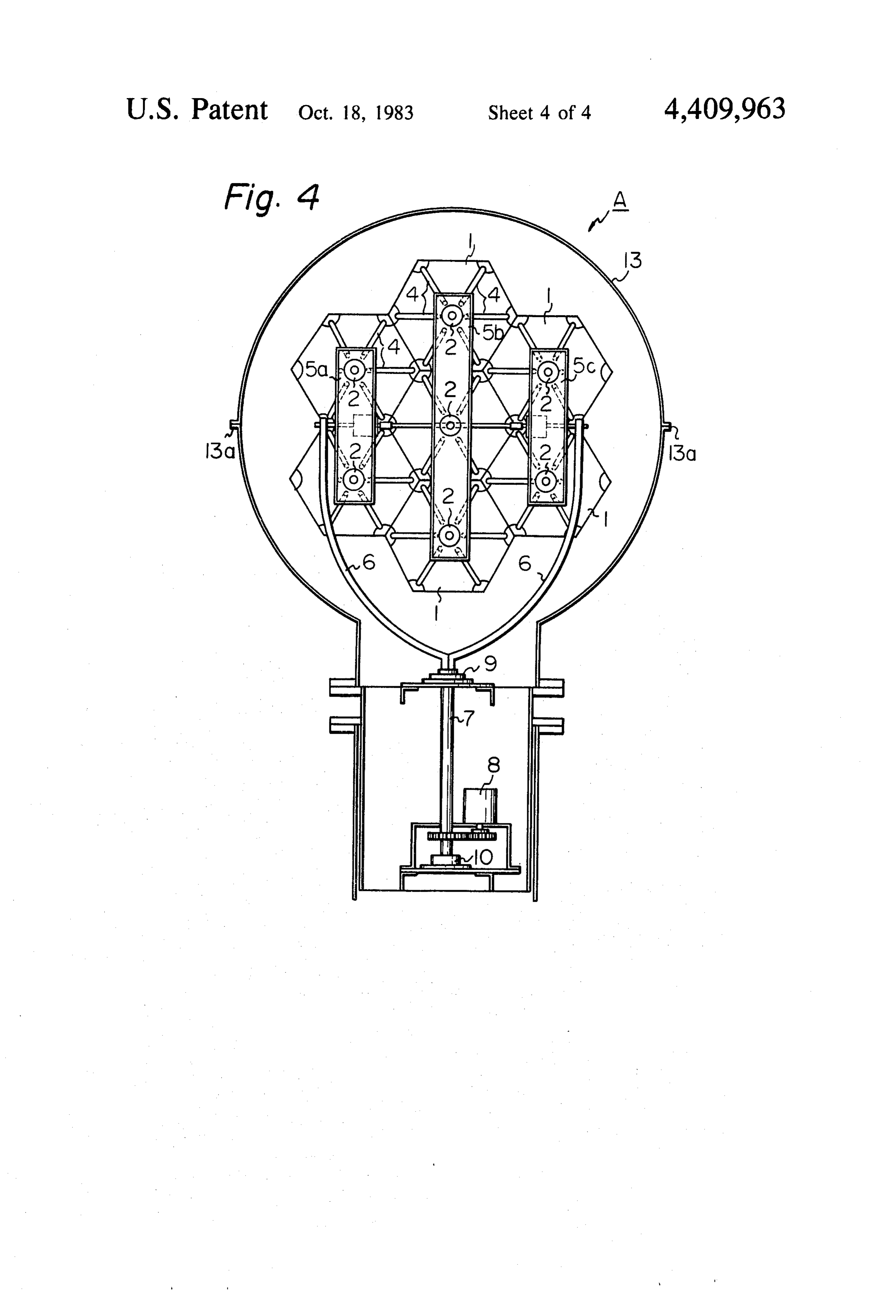
The way of carrying out the present invention is As a result of the above mentioned construction, the described in detail below with reference to several 50 operation of causing the Fresnel lenses to automatically drawings which illustrate specific embodiments, in track the movement of the sun so as to effectively col which: lect solar energy, can be performed by detecting the FIG. 1 is a front elevation diagrammatically illustrat position of the sun by means of the detecting device (not ing the structure of one embodiment of the solar optical shown), and by controlling the vertical and horizontal energy collector according to the present invention; 55 motors 8 and 12 in accordance with the output signals FIGS. 2 and 3 are side and rear elevation views, produced by said detecting device. respectively of FIG. 1; Although the invention has been described with re and FIG. 4 is a rear elevation, similar to FIG. 3, of an spect to an embodiment provided with seven Fresnel alternate embodiment of the solar optical energy collec lenses, it is to be understood that the present invention tor according to the present invention: 60 is not limited to said specific embodiment. For example, Referring to the drawings in detail, wherein like nu in addition to the embodiment illustrated in FIGS. 1 merals indicate like elements, there is shown a solar through 3, additional twelve Fresnel lenses can be dis optical energy collector in accordance with the present posed around the seven Fresnel lenses so that the num invention designated generally as symbol A. Solar opti ber of Fresnel lenses amounts to nineteen in all. Still cal energy collectors are mounted generally on the roof 65 further, in addition to the above, another eighteen Fres of a building (not shown). The building may be of any nel lenses can be disposed around the nineteen Fresnel type, however, solar optical energy collectors are espe lenses, so that the number of Fresnel lenses amounts to cially suitable for use on residential homes. thirty-seven in all. In a general sense, the constructive 7 number N of the Fresnel lenses according to the present the drawing, the capsule 13 is divided along a horizontal invention can be derived from the following equation: plane 13a-13a passing substantially through the center thereof.
In the case of the embodiment shown in FIGS. 1 through 3, the inlet diameter Ll of the spherical capsule wherein n stands for a natural number. 13 should be designed larger than the maximum width As stated above, according to the present invention, a L0 of the lens system, so as to receive the lens system et plurality of hexagonal Fresnel lenses, which can be al within said spherical capsule. Thus, the diameter of disposed without gaps therebetween, acts as a single such spherical capsule 13 becomes considerably large in lens having a configuration similar to a circle and thus a 10 S12c.
high efficiency of solar energy concentration is Contrary to the above, according to the alternate achieved. As the whole concentrating surface of the embodiment shown in FIG. 4, the diameter of the lens system is substantially a big circle, the present in spherical capsule 13 can be sufficiently designed with a vention results in the most effective arrangement of the slightly larger diameter than the maximum width Lo of Fresnel lenses. In addition, since the individual Fresnel 15 lens 1 has the focusing member 2, respectively, the focal the lens system. Consequently, the spherical capsule 13 distance of this lens system becomes remarkably shorter of FIG. 4 becomes smalier in comparison with that of than that of the conventional lens system with a single and FIGS. 1 through 3. Furthermore, since the assembling big Fresnel lens. Consequently, the present invention maintenancing operations of the collector can be provides a very compact solar optical energy collector. 20 performed after the upper half of the spherical capsule As can been seen in FIGS. 2 and 3, the lens system 13 has been removed, said operations are quite easy. together with the receiving system are hermetically Manufacturing of the collector is also easy. sealed in a transparent spherical capsule 13, so as to The invention has becn described in detail with par prevent the influence of the wind upon the latter. Since ticular reference to preferred embodiments thereof, but the lens system and the receiving system are sealed 25 it will be understood that reasonable variations and against the surroundings, dust or chemical substances modifications are possible without departing from the sticking to the lens system and disturbance of the auto spirit and scope of the invention.
matic sun tracking operation by wind are completely I claim:
prevented. Therefore, the lens system will not be pol 1. A solar optical energy collector, comprising a lens luted and efficiency will not be lowered by such sub 30 system for concentrating sun beams and a sun beam stances, nor its collecting efficiency be reduced. In the receiving system for introducing said sun beams into an Temperate Zone, the temperature within the capsule 13 optical-conductor cable, said lens system having a plu does not rise so much. This is because the capsule 13 has rality (N) of Fresnel lenses (1, 1 ...) each formed in the a big radiating surface per se, and the collected solar shape of a hexagon, with N=3n(n+1) Fresnel lenses (1, optical energy is transported by means of the optical 1...) being disposed around one Fresnel lens (1) so that conductor cable 3, and the remaining solar energy 35 each side of said one Fresnel lens (1) positioned in the which has failed to impinge on the lens system will pass center of said lens system adjoins one side of each of the through the transparent capsule 13 toward the sur respective surrounding Fresnel lenses (1, 1 . . . ), in a roundings, therefore, solar energy is not accumulated concentric-circular relationship wherein (n) stands for a within the capsule 13. Contrary to the above, in the 40 natural number; said sun beam receiving system having Torridor Frigid Zone, the temperature within the cap a plurality of sun beam focusing members (2, 2 . . . ) sule should be controlled. spaced from and rearward of said lens system, each of Furthermore, according to the present invention, the said sun beam focusing members (2) respectively corre lens system together with the receiving system are turn sponds to one of said Fresnel lenses (1), with said lens ably mounted around the vertical and horizontal shafts 45 system and said receiving system being integrated with 7 and 11 perpendicularly intersecting with each other at each other; a transparent spherical capsule (13), in the centroid of integrated both systems, so as to mini which said lens system together with said receiving mize gyrating mass of said integrated both systems. Said system are hermetically sealed, said lens system to centroid of integrated both systems is substantially posi gether tioned at the center of said spherical capsule 13. The mountedwith said receiving system being turnably around a vertical axis and a horizontal axis (7 operation of automatically tracking the movement of 50 and the sun can be performed very quickly and smoothly. other11), said axes perpendicularly intersecting each at the centroid of said integrated lens and receiv
Since the axis 7 and 11 respectively pass through the ing systems; and means for causing said lens system to centroid of integrated both of said systems, the Fresnel track the movement of the sun. lenses can collect solar energy uniformly. The gyration 55 2. A solar optical energy collector as claimed in claim torque thereof can be reduced to a minimum, and the 1, in which said transparent spherical capsule (13) is responding action of the solar optical energy collector formed of a plastic material divided along a horizontal can be effected quickly.
In view of the fact that the turning angle of the lens plane (13a, 13.b) passing substantially through the center system extends over 360°, the solar optical energy col thereof.
lector of the present invention may be utilized, for ex 60 3. Awhich solar optical energy collector as claimed in claim ample, in either the Northern or Southern hemisphere. 2,within said said centroid of said lens system together receiving system is positioned substantially at
Also, when said collector is mounted on ships or the like, the collector can be utilized without any trouble, as the center of said spherical capsule (13). the direction of the bow of said ship, on which the solar 4. A solar optical energy collector comprising a lens optical energy collector is usually mounted, can be 65 system for concentrating sun beams and a sun beam entirely disregarded. receiving system for introducing said sun beams into an FIG. 4 is a rear elevation showing an alternate em optical-conductor cable, said iens system having a plu bodiment of the present invention. As can be seen from rality (N) of Fresnel lenses (1, 1 ...) each formed in the 8 shape of a hexagon, with N=3n(n+1) Fresnel lenses (1, each other; a transparent spherical capsule (13) formed 1...) disposed around one Fresnel lens (1) so that each of a plastic material divided along a horizontal plane side of said one Fresnel lens (1) positioned in the center (13a,13b) passing substantially through the center of said lens system adjoins one side of each of the re thereof, said lens system together with said receiving spective surrounding Fresnel lenses (1, 1 . . . ), in a system being hermetically sealed in said spherical cap concentric-circular relationship, wherein (n) stands for sule (13) and turnably mounted around a vertical axis a natural number; said sun beam receiving system hav and a horizontal axis (7 and 11), said axes perpendicu ing a plurality of sun beam focusing members (2, 2 . . . larly intersecting each other at the centroid of said ) spaced from and rearward of said lens system, each of integrated lens system and receiving system, with said said sun beam focusing members (2) respectively corre 10 centroid positioned substantially at the center of said sponds to one of said Fresnel lenses (1), with said lens spherical capsule. k . . k sk system and said receiving system being integrated with
Provenance
- Collection
- Patents citing this work
- Pages
- 8
- Method
- pdftotext (the PDF's own text layer) + pdftoppm 300dpi page scans
- Patent office record
- patents.google.com →
- Source
- Google Patents citing-documents table
- Assignee
- Kei Mori
- Published
- 1983-10-18
- Transcribed from
- patentimages.storage.googleapis.com →