

patent · US4435662A
Axial air gap alternators/generators of modular construction
6 March 1984
Text
Page 1bibliographic recordscan →
United States Patent (19)
Tawse
54 AXIAL AIR GAP
MODULAR CONSTRUCTION
75 Inventor: Ian S. Tawse, Weston, Canada 73 Assignee: Gen-Tech, Inc., Miami, Fla.
Related U.S. Application Data
(51) Int. Cl'............................................. H02K 21/38 (52) U.S.C. .................................... 310/168; 310/268;
(58) Field of Search ................... 310/46, 156, 268, 44,
BRUSH GEAR AS PER. FIG
3,603,823 9/1971 Mason ................................... 310/46
4,059,777 1/1977 Whitely ........... ... 31.0/268 X 4,114,057 9/1978 Esters .................................. 310/266 4,187,441 2/1980 Oney .... ... 310/156 X 4,211,945 7/1980 Tawse .. ... 310/156 X 4,297,604 10/198 Tawse ............................. 310/268 X Primary Examiner-Donovan F. Duggan
Attorney, Agent, or Firm-Alan H. Levine
Alternators/generators of axially disposed air gap con formity in which a unique combination of rotors and stators results in machines of high efficiency, simplified modular assembly and extension. Such machines can, moreover, be readily constructed to produce from a single alternator unit multiple voltages and frequencies and from a single generator unit direct current in multi ple voltages.
6 Claims, 37 Drawing Figures
Spe
Drawings
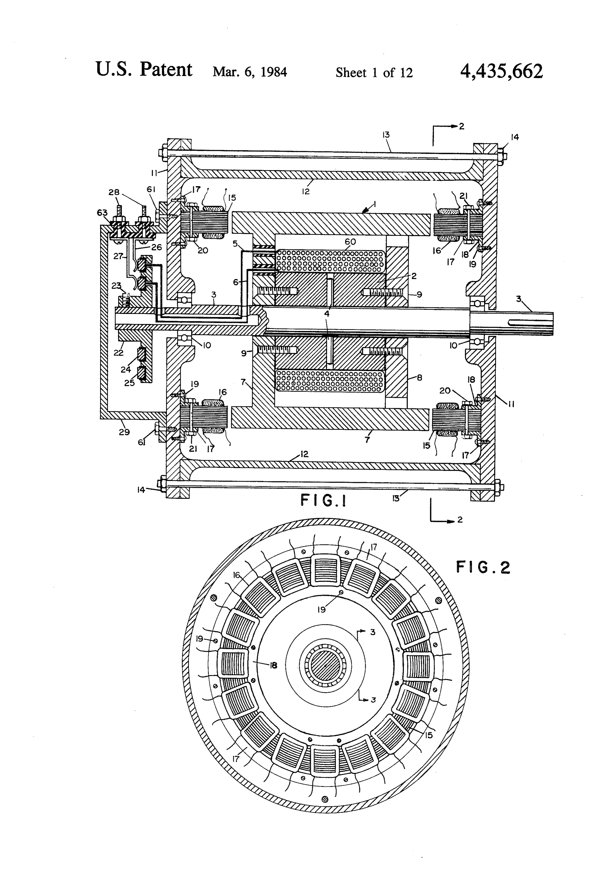

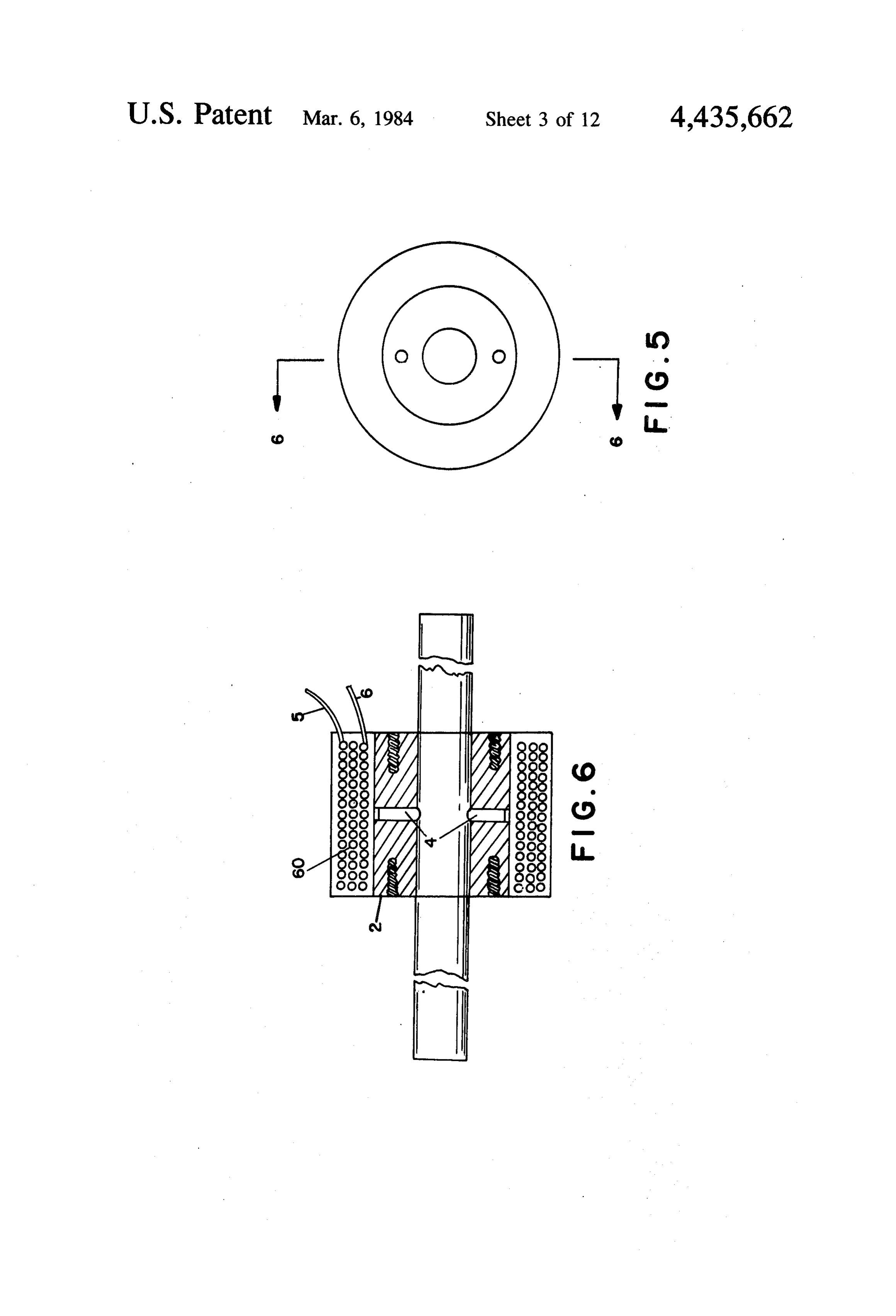
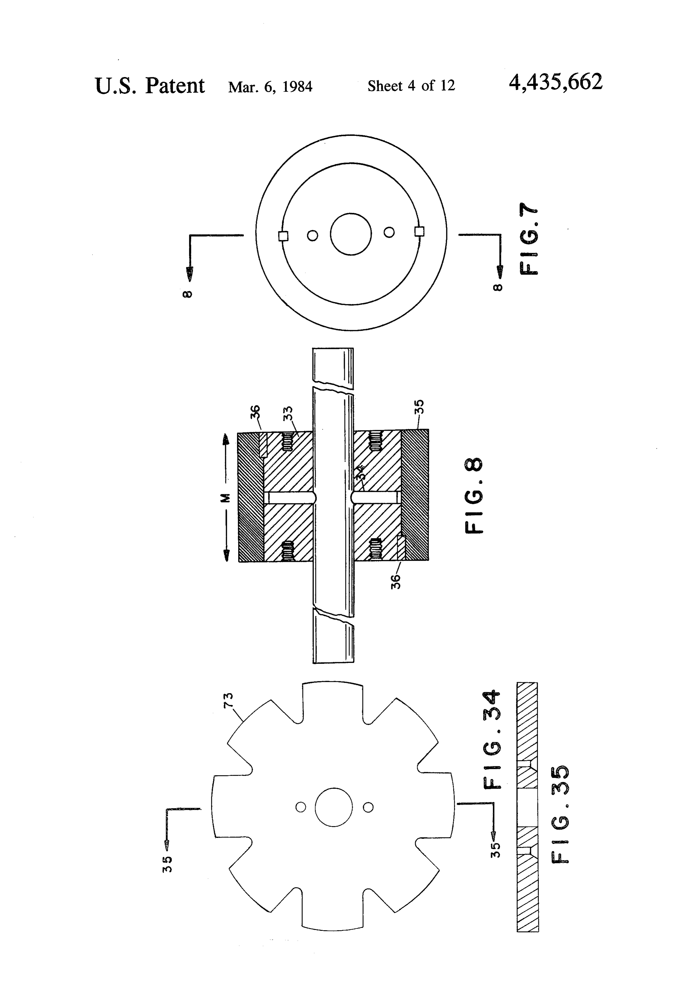
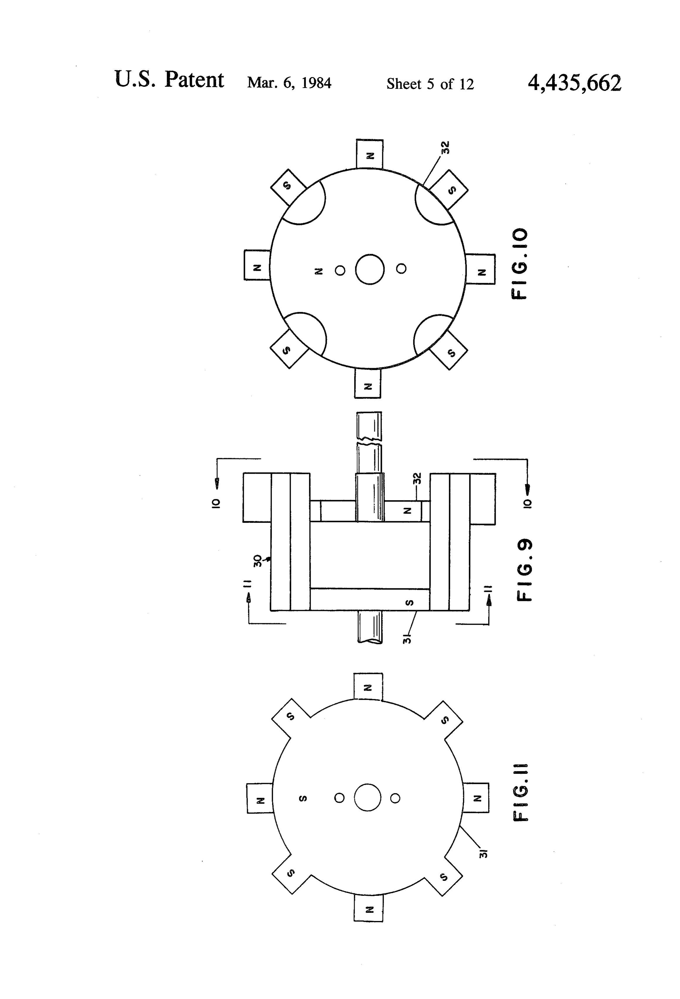
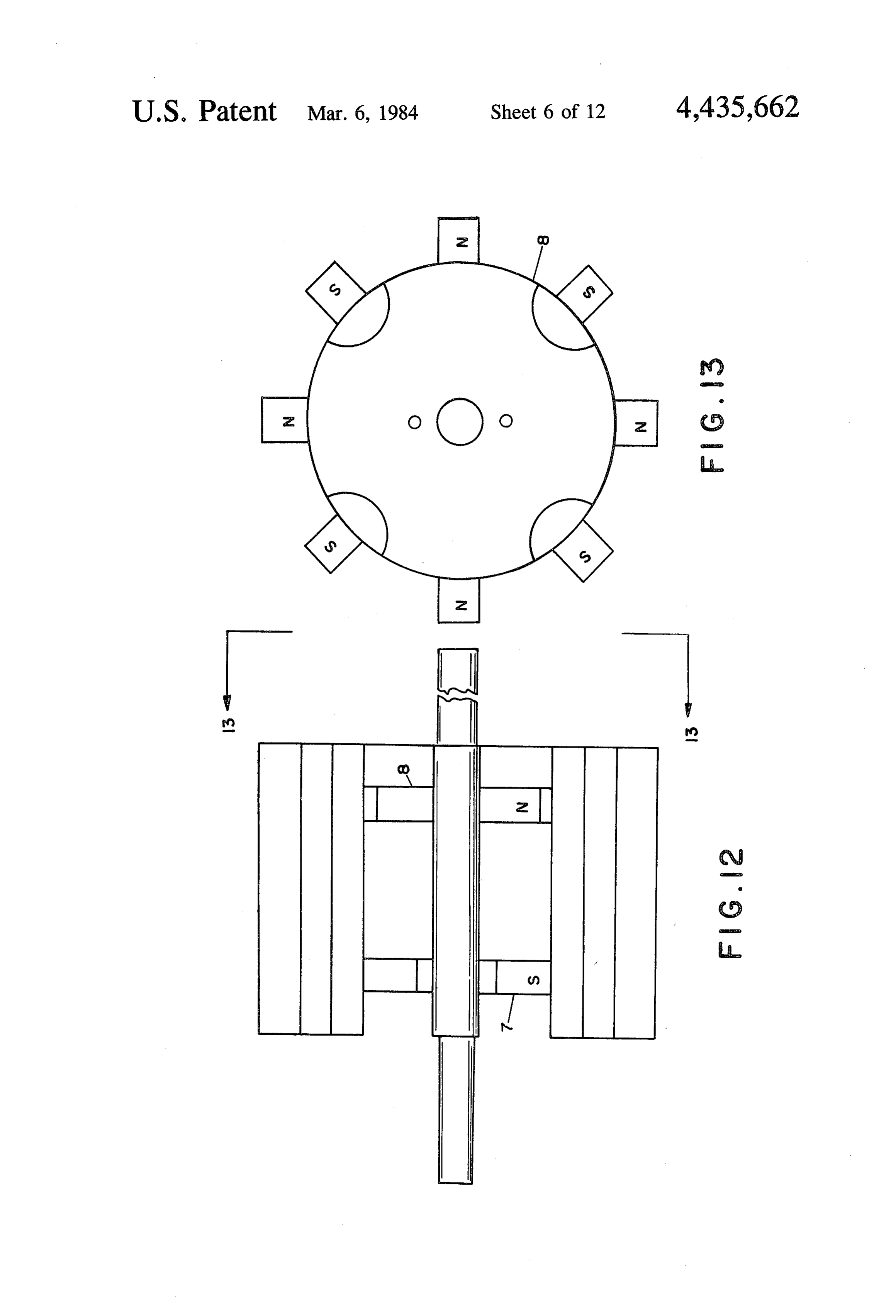
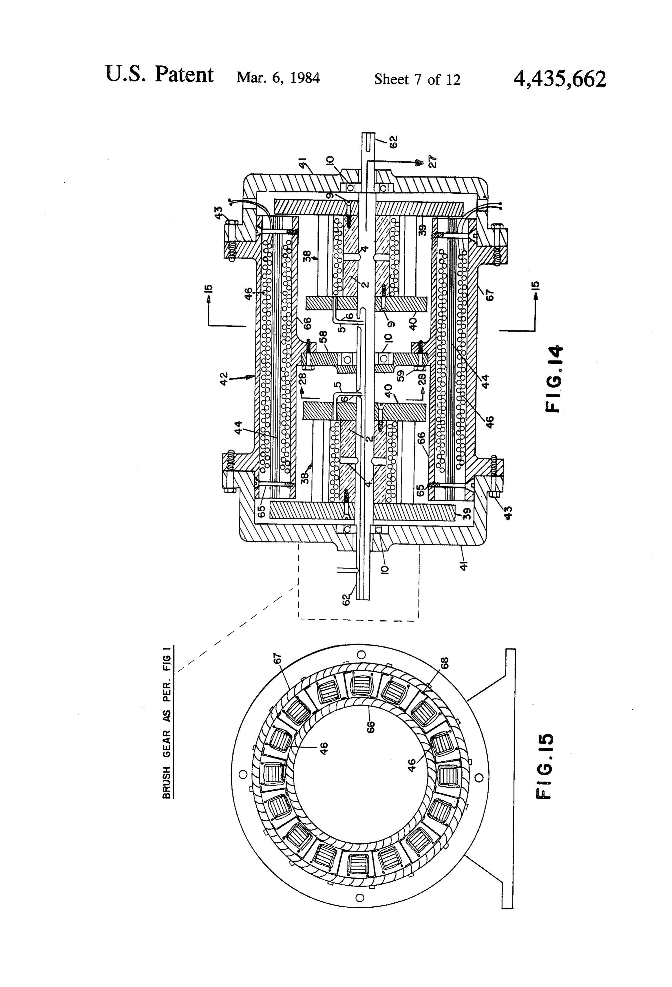
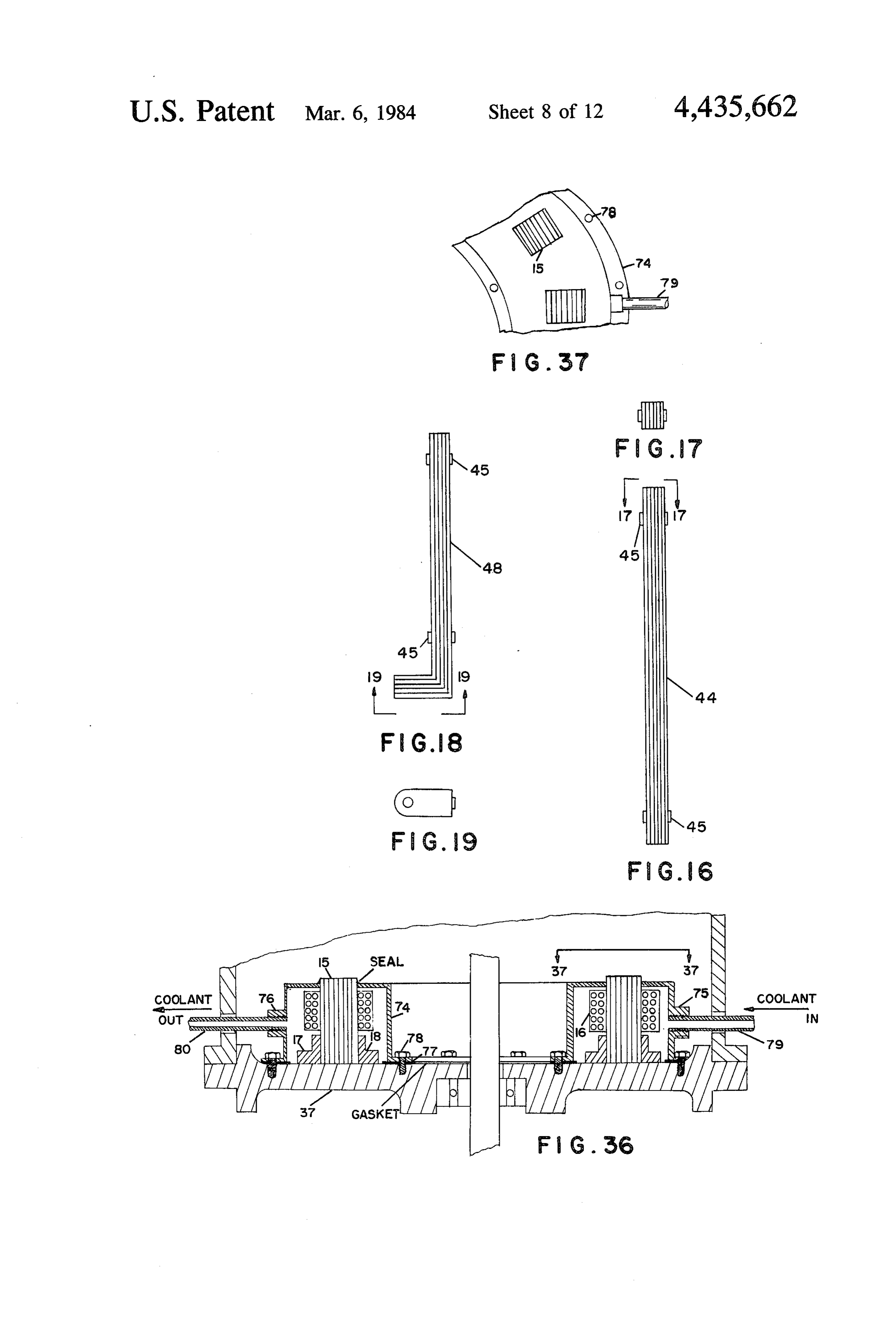
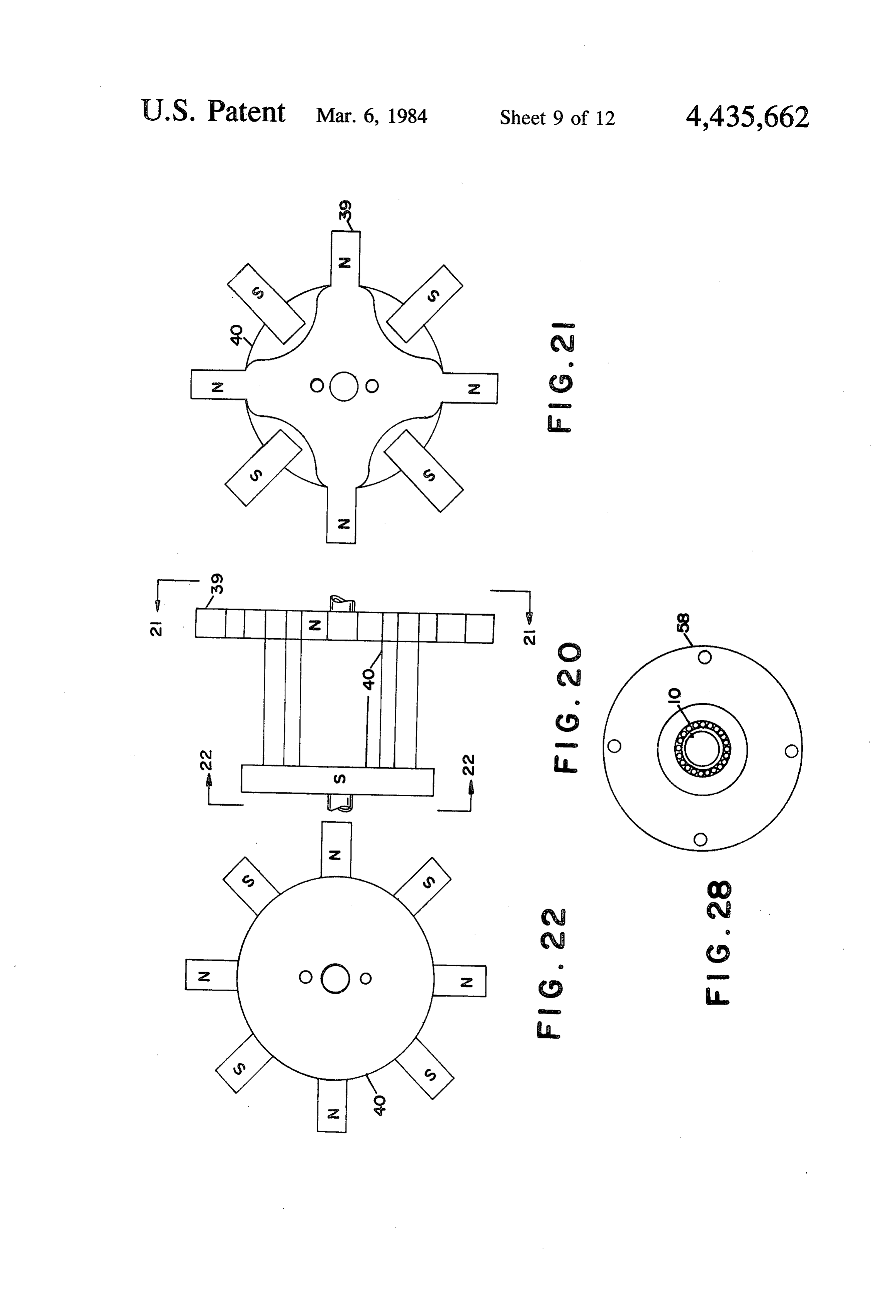
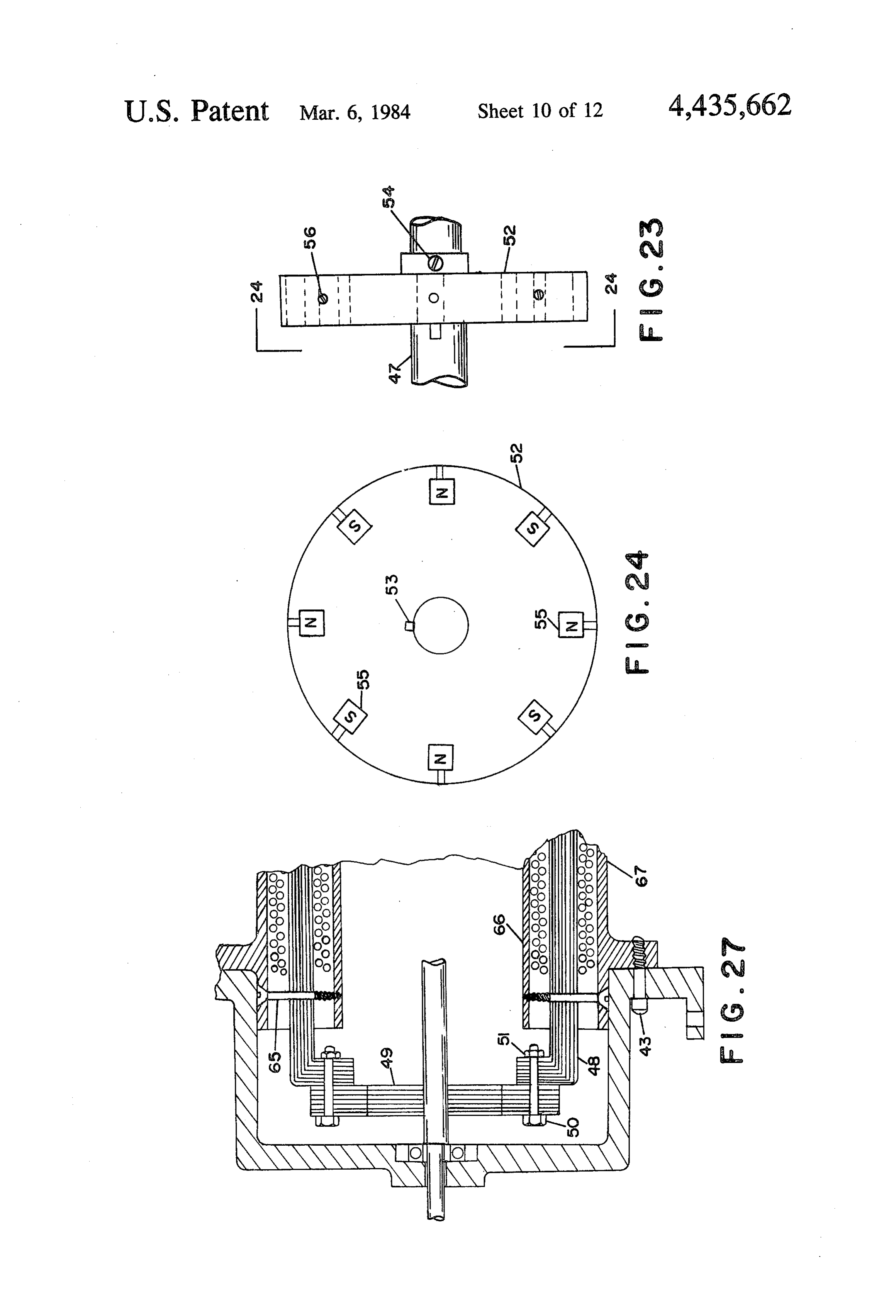
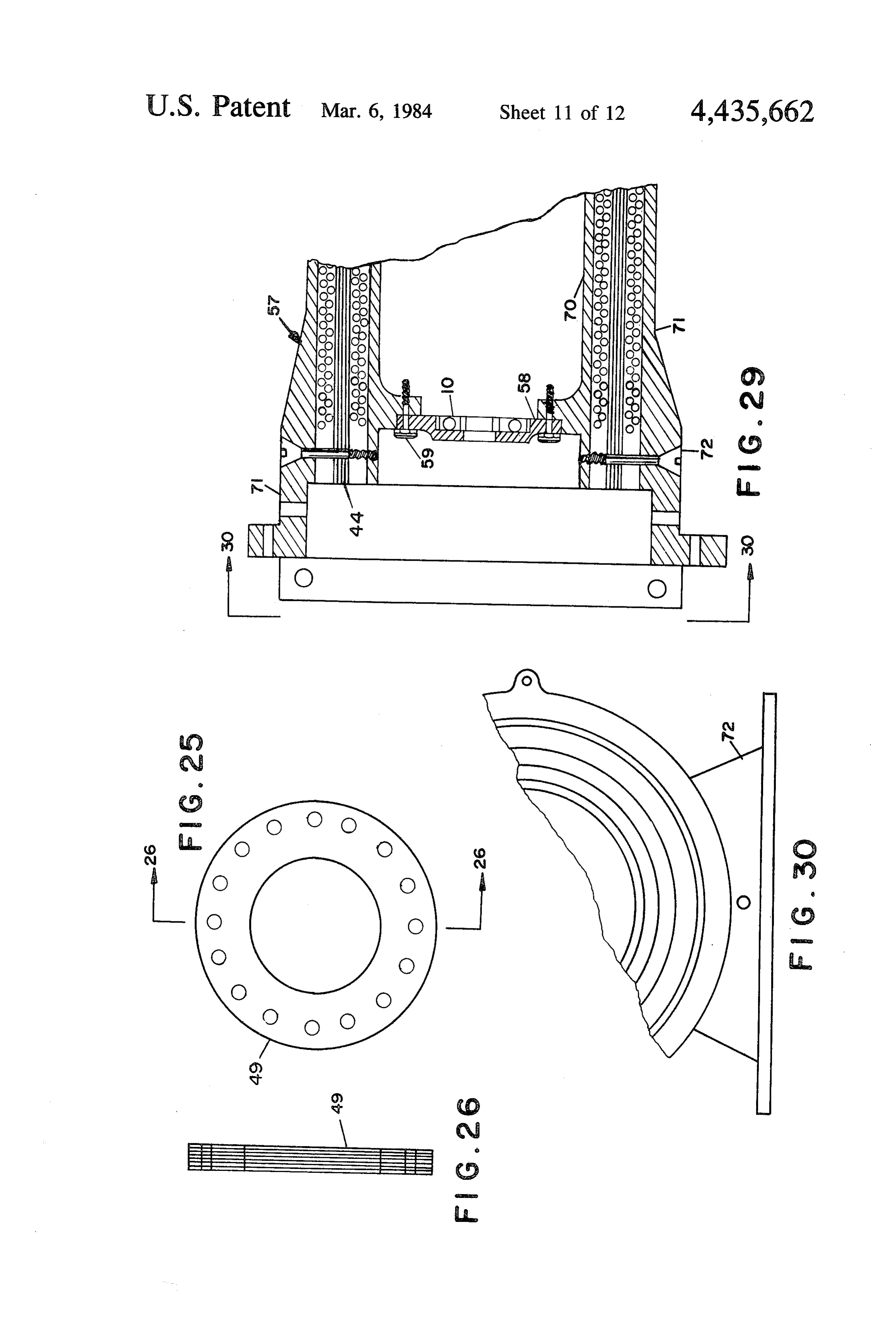
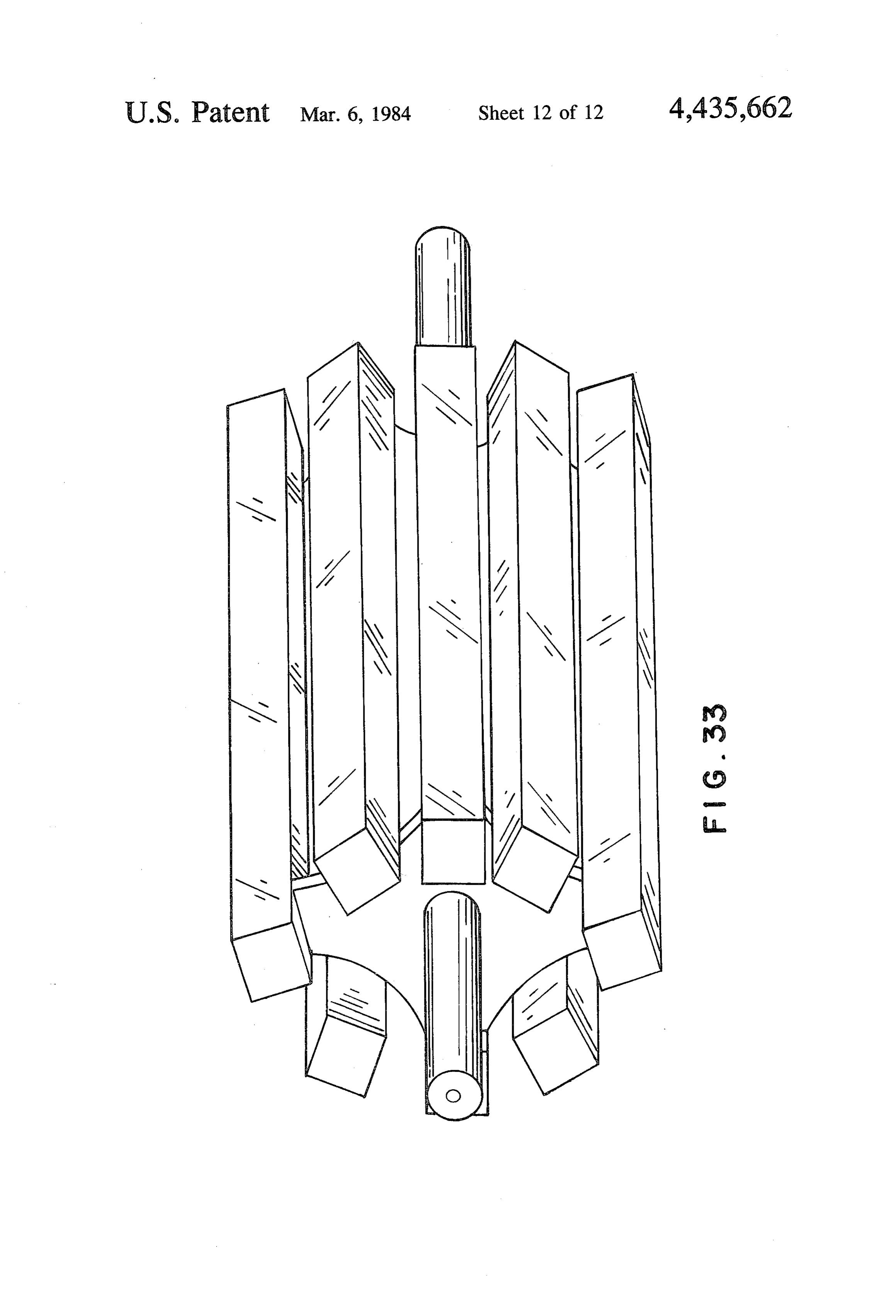
FIG. 27 is a fragmented sectional view generally on
Page 2drawing sheetscan →
Page 3drawing sheetscan →
Page 4drawing sheetscan →
Page 5drawing sheetscan →
Page 6drawing sheetscan →
Page 7drawing sheetscan →
Page 8drawing sheetscan →
Page 9drawing sheetscan →
Page 10drawing sheetscan →
Page 11drawing sheetscan →
Page 12drawing sheetscan →
Page 13drawing sheetscan →
Page 14scan →
cable to both Embodiments "A' and 'B' of the inven
AXAL AIR GAP ALTERNATORS/GENERATORS tion.
OF MODULAR CONSTRUCTION FIG. 6 is a longitudinal sectional view taken on Line 6 of FIG. S.
This application is a division of application Ser, No. 5 FIG. 7 is an end view on a shaft, non magnetic spacer 38,251, filed May 11, 1979, now U.S. Pat. No. 4,297,605. and ring type permanent magnet for a permanent mag This invention relates generally to alternators and net type rotor and is applicable to both Embodiments generators and in particular to the type wherein the 'A' and 'B' of the invention. cooperating magnetic components of rotor and stator FIG. 8 is a longitudinal sectional view taken on Line are set apart across an axially disposed air gap. 10 8 of FG. 7.
In keeping with my U.S. patent application Ser. No. FIG. 9 is a side view of a rotor pole unit for function 843,936 filed on Oct. 20, 1976, this invention is dedi in a single stator machine of Embodiment "A" confor cated to improvements in alternators/generators of the mity.
axial air gap type, with said improvements including the 15 FIG. 10 is an end view on FIG. 9 taken on Line 10. FIG. 11 is an end view on FIG. 9 taken on Line 11.
following more specific areas of objective endeavor;
Providing the capability to increase the capacity of FIG. 12 is a side view on a rotor pole unit for a multi machines of the type referred to by modular extension, ple stator machine of Embodiment "A" conformity. FIG. 13 is an end view on FIG. 12 taken on Line 13.
with added modules possessing similar or dissimilar FIG. 14 is a longitudinal sectional view showing the characteristics of voltage, frequency and current to the 20 salient components and their relationship to each other existing module or modules.
Providing the capability of producing electrical en as FIG. applies to Embodiment "B" of the invention. ergy of divergent voltages, frequencies and current FIG. 1415foristhe a cross sectional view taken on Line 15 of purpose of showing the radial orienta from single modules.
Providing single units having rotors of both perma 25 the unit's casing. iron tion of the stator and coils and their location within the interest of clarity the unit's rotor nent magnet and electromagnet conformity. has not been shown in this view. FIG. 15 applies only to Providing multi-pole rotors including high frequency Embodiment 'B' of the invention.
types from a single two pole ring or sleeve type perma FIG. 16 is a side view of a stator iron "bundle' for a nent magnet. multiple rotor machine of Embodiment "B" confor Providing multi-pole rotors including a high fre 30 mity.
quency type from a single coil electromagnet.
Providing magnetic iron of simplified configuration 17.FIG. 17 is an end view of FIG. 16 as viewed on Line including a castable type. FIG. 18 shows a stator iron "bundle' for a single Providing windings of simplified configuration. rotor machine of Embodiment "B" conformity. Providing a means of cooling the output windings of s. FIG. 19 is an end view on F.G. 18 as taken on Line an alternator/generator by placing the windings in di 19.
rect contact with a cooling liquid or gas. FIG. 20 is a side view of a rotor pole unit assembly In the invention as outlined within this specification applicable to Embodiment "B" of the invention. and the accompanying drawings, two cardinal embodi FIG. 21 is an end view on FIG. 20 as taken on Line ments of the invention are evidenced and will hereinaf 21.
ter be referred to respectively as Embodiment "A" and FIG. 22 is an end view on FIG. 20 as taken on Line Embodiment “B”, with Embodiment "A' being shown 22.
in main in FIG. 1 and Embodiment “B” being shown in FIG. 23 is a side view of a permanent magnet type main in FIG. 14. In Embodiment 'A' the path for mag rotor applicable to both Embodiments "A" and "B" of netic flux return is provided by the stator iron only, 45 the invention.
while in Embodiment “B” the magnetic flux is in gen FIG. 24 is a face view on FIG. 23 taken on Line 24. eral returned by means of rotor interaction. However, a FIG. 25 is a front view on a flux return ring of lami variant of Embodiment “B” as illustratively shown in nated construction and applicable to Embodiment "B" FIG. 27 provides means for flux return via the stator of the invention.
iron. 50 FIG, 26 is a longitudinal sectional view on FIG. 25 GENERAL DESCRIPTION OF THE DRAWINGS taken on Line 26.
FIG. 27 is a fragmented sectional view generally on
FIG. 1 is a longitudinal sectional view showing cer Line 27 of FIG.14 and supplements FIG. 14 to the tain principal features of the invention as applied to extent that it shows a flux return ring in location and Embodiment 'A'. The magnetic field herein is indi 55 moreover provides detail of the machine's support foot cated as being furnished by an electromagnet. which forms an integrated part of the end cap. FIG. 2 is a cross sectional view taken on Line 2 of FIG. 28 shows an intermediate rotor support as FIG. 1 for the purpose of showing the radial orientation would be generally viewed on Line 28 of FIG. 14. This and location of the stator iron and coils. figure is applicable to Embodiment "B" of the invention FIG. 3 is a fragmented view taken on Line 3 of FIG. 60 only.
2 and shows further detail of the stator iron with the FIG.29 is a longitudinal fragmented section showing output coils removed. details of a casing end which has been modified to allow FIG. 4 is a sectional view on an intermediate stator for modular extension of a machine constructed in ac plate and includes details of the stator iron and securing cordance with Embodiment 'B' of the invention. means for same. This detail is applicable to Embodiment 65 FIG. 30 is a fragmented view taken on Line 30 of “A” only. FIG. 29 and mainly serves to show detail of the ma FIG. 5 is an end view on a shaft, solecore and field chine's support foot incorporated in the casing end as coil assembly for an electromagnetic rotor and is appli- . reflected in FIG. 29.
Page 15scan →
FIG.31 is a fragmented cross sectional view on the 27. All brush gear components are protected by brush casing of a machine of Embodiment "B" conformity, gear cover 29 which is secured to end plate 11 by secur and shows the means of securing the outer casing to the ing screws 61. Brush gear terminal posts 28 are insulated inner casing. from brush gear cover 29 by insulator 63. FIG. 32 is a longitudinal sectional view taken on Line In order to usefully direct the magnetic field eminat 32 of FIG. 31 showing additional detail to that given in ing from the basic two-pole, two-pole face magnet FIG. 31. . .. .. . . . formed by the cooperation of field coil 60 and solecore FIG. 33 is an isometric view of a rotor pole unit 2, a pair of special rotor pole unit 7 and 8 (shown in assembly of the type shown in FIG. 12 and which has FIG. 12) of magnetic material have been provided and been provided in order to show greater detail of the 10 secured to the pole faces of solecore 2 by securing means whereby dissimilar polarities are obtained at one screws 9. The rotor pole units 7 aand 8 are constructed face of a basic electromagnet as shown in FIGS. 6 and as follows:
8. A disc which has its diametrical dimension placed at FIG. 34 is afront view showing details of a rotor pole 90 to the longitudinal axis of solecore 2, incorporates unit. to be used in a machine of Embodiment 'B' con 15 substantially at its periphery a plurality of fore and aft formity for the production of direct current electricity. directed fingers of square or rectangular cross section, FIG. 35 is a cross sectional view on FIG. 34 as taken said fingers being radially disposed with regard to the on Line 35. , longitudinal center line of solecore 2 and equally spaced FIG. 36 is a sectional view on a stator. plate and about said disc's periphery.
shows means whereby a coolant can be placed in 20 By reference to FIGS. 1 and 12 it will be noted that contact with the output coils, or windings of a machine the above referred to fingers are of unequal extension of Embodiment "A" conformity. fore and aft of the faces of the disc with which they are FIG. 37 is a fragmented view taken on Line 37 of integrated, and have their major length of extension FIG. 36. equal to the longitudinal dimension of the solecore 2 25 plus the dimension of the reciprocal extension as mea
DETAILED DESCRIPTION OF THE sured from the face of the disc establishing contact with DRAWINGS AND EMBODIMENTS OF THE the pole face of solecore 2. By referring to FIGS. 12 and
13 it will, moreover, be noted that crescent shaped
In FIG. 1 of the drawings the main components of an openings are in evidence in that portion of the pole unit alternator/generator of Embodiment "A" conformity 30 disc located adjacent to its periphery, and with the are shown, with said components being located in fuc radial center lines of said openings being spaced at equal tional relationship to each other. ; distance between each pair of fingers integrated with ... A casing 12 of cylindrical conformity has its ends the disc in which the openings are evidenced. The pur prepared to receive and accomodate end plates 11, said pose of the afore discussed openings is to receive the end plates being of a nonmagnetic material and serving 35 fingers or poles, of a pole unit of equated physical struc the multiple purposes of structurally supporting casing ture, located at the opposite end of the solecore 2 and 12, retaining bearing means 10 and structurally support secured thereto.
ing and retaining a ring of laminated magnetic metal 15 Since the fingers of the pole units located at opposite hereafter referred to as the "stator iron”, said stator iron ends of the solecore 2 will obviously be of opposite 15 being secured to the end plate 11 via the medium of 40 polarities, the crescent shaped openings are dimension stator iron securing ring (outer) 17 and stator iron secur ally calculated to eliminate magnetic short circuitry and ing ring (inner) 18, said rings 17 and 18 being con to minimize flux leakage between pole assemblies. structed of non magnetic material and fastened to end In function as a multi-pole rotor assembly 1 of the plate 11 by securing screws 19. The stator iron 15 is in electromagnetic type, the magnetic field eminating turn retained between securing rings 17 and 18 by bolt 45 from the north pole of solecore 2 (the appropriate direc 20 and nut 21, both of said items being of non magnetic tion of winding field coil 60 being observed) is trans material. A study of FIGS. 1 and 2 will further show ferred to the disc portion of rotor pole unit 8 from that stator inductor coils 16 are wound about the teeth which the field then flows via the pole fingers of said of the stator iron 15, said teeth being shown in greater rotor pole unit 8 in both directions of extension of said : detail in FIG. 3. Referring again to FIG. 1 it will be 50 fingers, then flows to the south pole face of solecore 2 noted that bearing 10 locates and retains a rotatable via the air gap at both stators, aligning teeth of the shaft.3 of non magnetic material to which a rotor assem stator iron 15, and fingers of rotor pole unit 7. It will be bly 1 of the electromagnetic type is secured by retaining noted that while the fore and aft extension of any pole screws 4, said screws being of magnetic material. finger is unequal, the total distance of flux flow from a In considering the construction of the rotor assembly 55 north to a south pole transverses an equal distance and 1, FIGS. 5 and 6 detail a solecore 2, of magnetic mate an equal volume of magnetic material. The reluctance rial, having a coil of wire 60 wound about its periphery of the magnetic circuit is therefore in balance. and across its length for the purpose of co-operating FIGS. 9, 10, and 11 reflect a modified version of the with the solecore 2 to create a magnetic field, the north rotor pole unit as afore discussed and as shown in FIGS. to-south and south-to-north orientation of which would 60 1, 12, 13 and 33. The modified version, comprising part parallel the rotor shaft 3. Coil 60 is provided with termi of rotor assembly 30, is designed for operation in ma nals 5 and 6 which are led through a hollow section of chines of single stator conformity and varies from the shaft 3 to brush gear rings 24 and 25 which are retained earlier discussed pole units 7 and 8 mainly in that the by an insulating cement (not enumerated) in a ring gear pole fingers extend in one common direction only from body 22 which in turn is screwed to rotatable shaft 3 by 65. the disc portions with which they are integrated. The securing screw 23. Direct current electrical supply to individual rotor pole units enumerated 31 and 32 respec coil 60 is led (from a source not shown) to brush gear tively, moreover have pole fingers of unequal length, 31 rings 24 and 25 via terminal posts 28 and brushes 26 and having the longer fingers in view of their having to 16 traverse the length of the solecore 2, in order to main system components for the production of usable electri tain the pole faces of both magnet polarities in a com cal energy.
mon plane. It should be noted that the modified pole In considering the four rotor types dealt with in the units 31 and 32 have been conceptually structured to foregoing, it will be apparent to those skilled in the utilize the same solecore 2, and field coil 60, as rotor alternator/generator art that adequately constructed pole units 7 and 8 in order to form a complete electro rotors of the conceptual principles afore discussed, hav magnet assembly 30 as required in the function of an ing their poles placed in rotational coincidence with alternator/generator variant of Embodiment "A" of the stator iron as aforedescribed and detailed in the draw invention. Both rotor pole units 31 and 32 are secured to 10 ings, will adequately cooperate with said stator iron to solecore 2 by securing screws 9. produce a magnetic flux within the teeth or poles of the A modification to both types of rotors as previously stator iron which in turn will react with the induction described is as follows: coils 16 to produce electrical energy in the form of A spacer sleeve of non magnetic material 33, as alternating current.
shown in FIGS. 7 and 8 is substituted for solecore 2 and In order to reduce manufacturing costs and expedite is affixed to rotatable shaft 3 by securing screws 34, said 15 unit assembly on a machine of Embodiment 'A' con securing screws also being of a non magnetic material. formity, the following means of increasing output ca A permanent magnet of ring or sleeve conformity 35, pacity by simple addition of standardized components suitably dimensioned and magnetized in the direction hasInbeen FIG.
developed and is a feature of this invention.
4 a stator plate 37 of general configuratory indicated thus "e-M->' and being of material such as cast Alnico VIII (but not necessarily restricted to same) 20 similarity to stator plate 11 is indicated. It will be noted is substituted for field coil 60 and is secured to spacer however, that plate 37 has both of its faces prepared to sleeve 33 by tapered keys 36. In this modification to the receive a casing section 12 and has stator iron 15 se cured to both of its faces by securing rings 17 and 18, rotors as previously discussed, rotor pole units 7, 8, 31 and a bearing 64 is moreover positioned and retained in and 32 remain unchanged and said units would be se 25 accordance with details indicated for end plate 11. In cured to spacer sleeve 33 by securing screws 9. By the substitution of spacer sleeve 33 and permanent magnet order to increase the output capacity of a machine by 35 for solecore 2 and field coil 60, field coil terminals 5 modular extension, one end plate 11 would be omitted from a unit assembly and replaced with an intermediate and 6, brush gear rings 24 and 25, ring gear body 22, stator securing screw 23, brushes 26 and 27, brush gear termi 30 rotor ofplate 37. If the unit to be extended employs a nal posts 28, brush gear cover 29, securing screws 61 11 wouldthe be electromagnet type, the omitted end plate the one at the opposite end to the machine's and insulator 63 are eliminated from function in an alter nator/generator of Embodiment "A' conformity. brush gear assembly. In all instances of modular exten Yet another type of rotor highly suitable for provid sion the unit's shaft 3, or 47, dependent upon the type of rotor to be used, would be suitably extended in its longi ing the necessary magnetic field for an alternator/gen 35, tudinal dimension and in the case of a shaft for a ma erator of Embodiment “A” conformity is shown in chine utilizing a rotor of the electromagnetic type, the FIGS. 23 and 24. In this latter instance, a disc of non hollow section which accommodates the rotors' termi magnetic material 52 plurality of permanent magnets 55, nal leads 5 and 6 would also be suitably extended. With of square or rectangular cross sectional geometry, ap the installation of a suitably extended shaft 3 or 47, and proximating in said geometry and area, the cross sec having located and secured same at one end of the ma tional geometry and area of the stator iron teeth. Said chine, in an end plate 11, said end plate being located in permanent magnets 55 being longitudinally dimen suitable relationship to a casing segment 12, a rotor of sioned in accordance with design conditions and the the required type would then be located and secured to individual permanent magnets 55 located in suitably the sized openings arranged on a pitch circle substantially 45 nowunit's shaft, an intermediate stator plate 37 would be installed, followed by a further rotor of suitable coincident with the pitch circle of the stator iron 15. conformity, and in the case of a machine of two rotor/- The permanent magnets 55 are retained in their ac four stator configuration, a suitably dimensioned casing comodating openings by securing screws 56, said secur segment 12 and a further end plate 11. Casing segment ing screws being of non magnetic material. By referring 12, stator and plates 11 and intermediate stator plate 37, to FIG. 24 it will be seen that the permanent magnets 55 50 would now be secured by properly dimensioned tie rods are of an equal angular disposement about the faces of 13 together with securing nuts 14. In an assembly as last disc 52 and are of alternating magnetic polarities. described, it should be noted that rotor stability is virtu In utilizing a rotor of the type last described within ally assured by the intermediate bearing 64, and assum the confines of an alternator/generator of Embodiment ing equal air gaps between the faces of the rotor and 'A' conformity, the previously described rotors, shaft 55 stator iron, no end loads would be impsed upon the ing and brush gear components would be excluded from bearings 10 and/or 64.
the assembly and replaced with a permanent magnet In the example of modular extension cited in the type rotor 52, said rotor incorporating in its structure a foregoing, a situation considering a two rotor/four hub and keyway as shown in FIGS. 23 and 24. In an stator unit has been dealt with, but it would be obvious operable installation, rotor 52 would be affixed to a that unit extensions exceeding the quantity of rotors and suitably dimensioned rotatable shaft 47 by means of key stators cited in the example is possible, but in such in 53 and securing screw 54. Shaft 47 would be located stance, longitudinal reinforcement of a unit's casing (not and retained by bearing means 10. Such an installation shown) would be required to establish structural stabil in combination with suitably dimensioned casing 12 and ity of a machine of yet further extended modular config tie rods 13 would place the rotor 52 in a centralized 65 uration. It would also be apparent that by omitting position between stator iron 15 located at both ends of stator iron 15, induction coils 16, stator iron securing the alternator, in which position the rotor when re rings 17 and 18 together with securing screws 19, bolt volved by a suitable driver would cooperate with other 20 and nut 21 from one and plate 11 and utilizing a rotor 17 assembly 30, of a permanent magnet type rotor 52, in It should be noted that while the example of system conjunction with a suitably dimensioned casing 12 and cooling means dealt with in the foregoing refers to and likewise suitably dimensioned tie rods 13, a foreshort details cooling of the output coils on one side of a stator ened single stator machine would be constructable. plate 37 only, it would be readily understandable that Moreover in constructing a machine or modular exten such cooling means could be applied to both sides of an sion, it would also be apparent that rotors of divergent intermediate stator plate 37 and/or to a stator end plate types and/or of different pole numbers could readily be 11, thereby making possible the cooling of the output incorporated in a single assembly making practical a coils in a alternators/generators of modular extension. wide variety and range of output conditions. In FIG. 14 a longitudinal cross sectional view of the A further feature of the invention as applicable to 10 second major embodiment of the invention hereafter Embodiment 'A' of same is a means whereby cooling referred to as Embodiment "B" is shown. In this view of the machine's output coils can be achieved. certain major components of this latter embodiment of In FIG. 36 a typical stator plate 37 is indicated, said the invention are shown in their relationship to each plate carrying stator iron 15, stator iron securing rings other.
17 and 18 together with output coils 16. It will be noted 15 In the afore referred to FIG. 14 a casing assembly 42, however that said items 15, 16, 17 and 18 have now been of non magnetic material is indicated, said casing com enclosed within a coolant containment area bounded in prising an inner section 66 of elongated cylindrical main by stator plate 37, gasket 77 and coolant contain form, contained within the confines of a radially set ment channel 74, said coolant containment channel 74 apart outer section 67, also of elongated cylindrical (constructed of non magnetic material) and gasket 77 20 form, but having a pair of flanges encircling its periph being secured to stator plate 37 by securing screws 78. ery, said flanges being located in near proximity to its By further reference to FIGS. 36 and 37, the latter ends and having a plurality of tapped holes disposed figure serving to further detail the means whereby cool about their faces for the purpose of receiving bolts used ing of the output coils can be achieved, it will be dis to secure the machine's end closure means 41 to the cerned that the containment channel 74 comprises a 25 casing assembly 42. Also included in the casing assem channel of "doughnut' conformity having a plurality of bly 42, is a plurality of "Z' shaped rib members of non openings cut in the web member of said channel in magnetic material 68, such rib members having a longi order to receive the fingers of the stator iron 15, while tudinal dimension substantially equal to the longitudinal the channel sides at its open end bear outwardly di dimension of the casing inner and outer section 66 and rected integrated flanges encompassing the total devel 30 67. The said rib members 68 are shown in FIGS. 31 and oped length of the channel, said flanges being in pur 32 and function to maintain apart casing sections 66 and pose designed to facilitate the securing of the said con 67, and are in radial dispersement equidistant within the tainment channel 74 to the stator plate 37. The contain area separating the inner and outer casing sections 66 ment channel 74 is moreover provided with a coolant and 67. By further reference to FIGS. 31 and 32 it will inlet connection 75 and a coolant outlet connection 76, 35 be noted that rib member 68 is secured to inner casing both connections being integrated with said contain section 66 by spot welding and secured to casing outer ment channel 74 and provided with means for receiving section 67 by a plurality of securing bolts 69, said bolts the threaded ends of pipes functioning to supply and being the fourth and final item comprising the casing discharge the coolant received in the containment area. assembly 42.
In a machine provided with cooling means as de In FIGS. 16 and 17 a "bundle' of laminated magnetic scribed herein, the stator iron 15 and output coils 16 iron 44 is indicated, said magnetic iron being equal in its would be enclosed in an envelope of epoxy prior to longitudinal dimension to that of casing assembly 42, their being integrated with the stator plate 37 following and in cross sectional geometry being substantially of which the containment channel 74 would be located in rectangular conformity. FIG. 16 also indicates that the position with gaskets 77 being located between the 45 magnetic iron "bundle' 44 is maintained in unitary as flanges of said containment channel 74 and the stator sembly by retaining rivets 45, said rivets being of non plate 37. The containment channel 74 would now be magnetic material. By referring again to FIGS. 14 and secured to the stator plate 37 by securing screws 78, and 15 it will be noted that a plurality of laminated magnetic a fillet of epoxy would be applied to all areas of intersec iron "bundles' 44, having first had an induction coil 46 tion between the stator iron teeth and the web of the 50 wound about their outside surfaces, have been located containment channel 74 thereby forming a sealed con in the open area lying between the inner and outer tainment area except for the inlet and outlet connections casing sections 66 and 67 of casing assembly 42, and enumerated 75 and 76 respectively. retained therein by retaining screws 65, said screws Having secured the containment channel 74 in the being of non magnetic material.
manner as last described, a coolant inlet pipe 97 supply 55 The combined magnetic iron "bundles' 44 and induc ing coolant (from a source not shown) and a coolant tion coils 46 are in equal radial dispersement between outlet pipe 80 discharging the warmer coolant, both the inner and outer casing sections 66 and 67 of the having ingress to the containment channel 74 through casing assembly 42; and, in longitudinal location, the suitably dimensioned openings in casing 12 are threaded fore and aft faces of the iron "bundles' 44 are in coinci into coolant inlet and outlet connections 75 and 76, dence with the ends of the casing assembly 42. By refer thereby completing the construction of means whereby ring again to FIG. 14 it will be seen that twin rotor cooling of the output winding of a machine of Embodi assemblies 38, said rotor assemblies being of the electro ment 'A' conformity can be achieved. magnetic type, are provided in order to furnish the In consideration of the coolants utilizable for the necessary magnetic flux for interaction with the mag system as afore described, it would be apparent that 65 netic iron 44, and induction coils 46, in order to effect fluids in either liquid or gaseous states could be effec the generation of electrical energy. In considering the tively used provided adequate attention was given to construction of a rotor assembly 38, of the electromag details of temperature, velocity and flow volume. netic type as shown in FIG. 14, a solecore 2 and a field 18 coil 60 as shown in FIGS. 5 and 6, and as previously facilitating the securing of said means 41 to casing as described in relationship to Embodiment "A' of the sembly 42, and a bearing means 10, is retained about its invention, are suitably affixed to a rotatable shaft 62, center. By reference to FIG. 15 it will moreover be said shaft being of suitable dimension and provided with noted that a support foot for the purpose of supporting a hollow section in order to accomodate the terminal the machine's structure, or securing same to a base such leads 5 and 6 of the field coil 60, said leads being for the as the floor of a building, has been integrated in end cap purpose of supplying direct current electrical energy means 41. It should also be noted that when required, from a brush gear apparatus in all respects similar to openings may be incorporated in the end cap means 41 that described in relation to Embodiment 'A' of the for the purpose of bringing the terminals of the ma invention. O chine's output coils 46 to the outside of the machine. In order to direct the magnetic field eminating from Referring again to FIG. 14 and having described the simple two pole/two face magnet formed by the casing assembly 42, the rotor assemblies 38, intermedi cooperation of field coil 60 and solecore 2, to a single ate rotor support means 58 and 10, shaft 62, stator iron face magnet of multiple alternating north and south 44, inductor coils 46, end caps 41 and means of supply poles, a pair of dissimilar rotor pole units 39 and 40 are 15 ing direct current power to the rotor's field coils 60, and provided in accordance with details illustratively having described the methods whereby the immediately shown in FIGS. 20, 21 and 22. store listed components are located and secured in their In FIG. 21 a side view of a composite pole unit, con relationship to each other, it will be seen that by more sisting of north pole unit 39, and south pole unit 40 is in over securing end plate means 41, together with end evidence. In FIG. 21 a front view (from the north pole 20 bearings 10 to casing assembly 42 by bolts 43, a fun unit's face) shows the configuration of the north pole tional alternator/generator of Embodiment "B" confor unit as being in the form of a modified cross, the rela mity will have been constructed.
tionship of its secondary dimension, appearing in the It is important to note that in assembling a machine of form of a flat plate and bearing the designation "N" is Embodiment "B" conformity as shown in FIG. 14, and evidenced in FIG. 20. In an assembled rotor, the north 25 in order to provide a return path for the magnetic flux pole unit 39, could be centered about shaft 3, and se eminating from the north pole of rotor assemblies 58, cured to solecore 2 by securing screws 9. By referring said rotor assemblies should be affixed to the shaft 62 in again to FIGS. 20, 21 and 22 it will be seen that the such manner that fingers or poles of opposite polarity rotor's south pole unit 40, is of a more complex struc are at all times in lineal alignment; or as otherwise ex ture, consisting of a disc section incorporating in sub 30 pressed, opposing poles should at all times be coincident stantial proximity to its periphery, a plurality of fingers with the opposing ends of any magnetic iron "bundle' or poles, said fingers or poles being in equal radial dis 44.
persement about the periphery of said disc and extend As in the instance of machines of Embodiment 'A' ing in the direction of the rotor's north pole unit, to the conformities, rotors of divergent characteristics are first point of intersection with same, whereat, said fin 35. adaptable to the basic alternator/generator of Embodi gers are made to effect a 90° outward radial change of ment "B" conformity as shown in main in FIG. 14, and direction, bringing them into parallel alignment with substitutions as described in the following may be ef the rotor's north pole as viewed in FIG. 20. Upon being fected in order to achieve a certain condition of design centered with respect to solecore 2, the rotor pole unit requirement.
40 is secured to said solecore 2 with securing screws 9. A spacer sleeve of non magnetic material as shown in By referring again to FIG. 21 it will be seen that both the FIGS. 7 and 8 is substituted for solecore 2, and is affixed north and south poles of the rotor as assembled, are in to rotatable shaft 62 by securing screws 34, said secur radial symmetry and configuration of the north pole ing screws also being of a non magnetic material. A unit 39 is such as to circumvent magnetic short circuit permanent magnet of ring or sleeve conformity 35, ing to the fingers or poles of south pole unit 40. 45 suitably dimensioned and magnetized in the direction In order to impart structural stability to the rotating indicated thus "e-M->' and being of a material such as elements of a machine of the conformity reflected in Ainico VIII (but not necessarily restricted to same) is FIG. 14, an intermediate rotor support means has been substituted for field coil 60 and is secured to spacer provided, said rotor support means, shown in both sleeve by tapered keys 36. In this modification to rotor FIGS. 14 and 28 comprises bearing support plate 58 and 50 assemblies 38 as shown in FIG. 14, rotor pole units 39 bearing 10, bearing support plate 58 being of disc con and 40 would remain unchanged, and said units would formity with bearing 10 being retained about its center. be secured to spacer sleeve 33 by securing screws 9. By In function, the support element is located on the inside the substitution of spacer sleeve.33 and permanent mag of casing assembly 42, substantially equidistant from the net 35 for solecore 2, all means for supplying direct ends of said casing assembly, and is secured to said 55 current power to field coil 60 would be eliminated from casing assembly 42, by a plurality of bolts 59, the function.
threaded ends of which engage in an inwardly project Another type of rotor highly suitable for providing ing flange forming an integral part of inner casing 66. the necessary magnetic field for an alternator/generator Being so located and secured, and having bearing 10 of Embodiment “B” conformity is shown in FIGS. 23 encompassing shaft 62, it will be apparent that substan and 24. In this latter instance, a disc of non magnetic tial structural stability has been imparted to the ma material 52 has a plurality of permanent magnets 55, of chine's rotating elements by the afore described compo square or rectangular cross sectional geometry, approx nents. imating in said geometry and area the cross sectional Also shown in FIG. 14 is a pair of end plate or end geometry and area of the stator iron "bundles'. Said cap means 41, said means serving in main to integrate 65 permanent magnets 55 being longitudinally dimen the rotating and static elements of a machine of Em sioned in accordance with design conditions, and the bodiment "B" conformity. It will be noted that a flange individual permanent magnets 55 located in suitably section is embodied in said means 41 for the purpose of sized openings arranged on a pitch circle substantially 19 coincident with the pitch circle of the stator iron 44. In a modified version of the rotor as last described, The permanent magnets 55 are retained in their accom and again with the purpose of generating direct current modating openings by securing screws 56, said securing electrical power without resorting to collector brushes, screws being of non magnetic material. By referring to a suitably dimensioned rotor sub-assembly of permanent FIG. 24 it will be seen that the permanent magnets 55, magnet type, and comprising non magnetic sleeve 33, are of an equal angular disposement about the face of securing screws 34, sleeve or ring type permanent mag disc 52 and are of alternating magnetic polarities. nets 35, all as shown in FIG. 8 is substituted for solecore In utilizing rotors of the type now described within 2, securing screws 4, field coil 60 and all means of sup , the confines of an alternator/generator of Embodiment plying said field coil 60 with direct current power. In an "B' conformity, the previously described rotors, shaft O operating generator of Embodiment 'B' conformity, a ing and brush gear components would be included from pair of rotor pole units 73 being secured to non mag the assembly and replaced with permanent magnet type netic sleeve 33 by securing screws 9 would perform an rotors 52, said rotors incorporating in their structure a identical function to that described for the electromag hub and key as shown in FIGS. 23 and 24. In an opera 15 netic type rotor as last dealt with herein. ble installation, rotors 52, being located substantially in In reviewing the means whereby magnetic flow is the area occupied by rotor pole units 39 in FIG. 14, introduced to the stator iron of all variants or Embodi would be affixed to a suitably dimensioned rotatable ment "B" of the invention, as previously discussed, it shaft 62 by means of key 53 and securing screw 54. will be noted that in all instances, rotors or rotor pole Shaft 62 would be located and retained by bearing units have been located in rotatable circumstance at means 10 with said bearing means being retained in end 20 both ends of the stator iron "bundles' 44, with the pur plate 41. Upon securing end plates 41 to the casing pose of such arrangement being to ensure a path of assembly 42 by means of securing bolts 43, yet another magnetic flux return and/or to maximize machine out variant of Embodiment 'B' of the invention will have put. In the event, however, of a requirement for ma been constructed. chines of more limited outputs and/or due to circum In FIGS. 34 and 35 details of yet another rotor pole 25 stances of manufacture or economics, an alternative unit 73 is evidenced, the said pole unit, constructed of a method of obtaining flux return has been provided. In FIG. 18 an alternative form of stator iron to that magnetic material, has been conceptually structured to shown in FIG. 16 is in evidence. The iron "bundle' 48 cooperate with an electromagnet as formed by solecore 2 and field coil 60, shown in FIG. 6, and/or a permanent 30 shown in FIG. 18 is formed from laminates, retained in magnet 35, as shown in FIG. 8 in order to produce respectsassembly unitary by non magnetic rivets 45 and is in all similar to iron "bundle' 44 except that one of direct current electricity from a machine of Embodi its ends has been bent through 90' in order to form a ment "B" conformity without resorting to output col figure of "L' shaped conformity. It will moreover be lector brushes. By examination of FIGS. 34 and 35, it noted by again referring to FIG. 18 that a punched hole will be noted that pole unit 73 is of modified disc con formity, having a plurality of equally spaced and geo 35 is"bundle" in evidence in the shorter leg of the "L' shaped iron metrically and dimensionally equated "cut outs' ex to the end48, of said hole being located in near proximity said iron "bundle'. In FIG. 27, the method tending inward from the periphery of the disc, and of installing the modified serving to define a plurality of outwardly directed fin rotor machine is indicated.ironIt "bundles' 48 in a single will be noted that the gers, the radial centerlines of said fingers being of equal shorter leg of the "L' shaped iron “bundles' 48 is angular dispersement. In function as an electromagnetic turned inward towards the machine's axis and in all type rotor, a pair of pole unit 73, located within the instances would be located at the end of the machine confines of a machine of Embodiment "B" conformity, opposite to the rotor and/or brush gear. In FIGS. 25 and placed substantially in the arms occupied by rotor and pole units 39 as shown in FIG.14, would be secured to 45 cated,26 said a flat ring of laminated magnetic iron 49 is indi ring having a plurality of holes disposed solecore 2 by securing screws 9. , , about its face on a pitch circle coincident with the pitch In this instance, solecore 2 (which would be secured circle established by the holes contained in the shorter to shaft 62 by securing screws 4) and field coil 60 would leg of stator iron "bundles' 48 when installed in casing be of such longitudinal dimension as to span the length assembly 42 as previously described and as shown in of the stator iron "bundles' 44, plus the sum of the air 50 FIG. 27. By cross reference of FIGS. 15 and 25 it will gap dimension at both ends of the stator iron. In further be noted that the number of holes contained in the lami consideration of the rotor pole units 73, it should be nated iron ring 49 is equal to the number of laminated noted that the arc length of the fingers of said pole unit stator iron "bundles' for a typical machine, thereby 73, as measured on a pitch circle coincident with the facilitating the affixment of the individual stator iron pitch circle of the center line of the stator iron, as 55 "bundles' viewed in FIG. 15, would be such as to ensure that at bolts 50 and48securing to the laminated iron ring 49 by locating nuts 51 in the manner as shown in any given time, a minimum of 50% of the stator iron FIG. 27. Having secured "bundles', as viewed in cross section from the air gap, the laminated iron ring 49the stator iron “bundles' 48 to would be covered by the said pole unit fingers. In an 51, said bolts and nuts being ofmeans a non of bolts 50 and nuts magnetic material, operating generator utilizing a rotor as last described, an adequate return path for the magnetic flux emanating said rotor being supplied with direct current power to from the machine's rotor will have been established its field coil 60, in a manner as previously described without the incurrence of abnormal losses to residual herein, the rotor pole units 73, by the nature of their magnetism.
configuration, would create periodic variations in the As in the instance of Embodiment 'A' of the inven intensity of the magnetic field as they are revolved, and 65 tion, and in order to make available machines capable of thereby create an interaction with the stator iron 44 and providing a side range of output conditions of voltage, the induction coils 46 of such nature as to result in the current and frequency from a single machine whilst production of direct current electrical power. utilizing standardized components in its assembly, a 20 method of modular extension as hereinafter described In the example of modular extension cited in the has been evolved for machines of Embodiment 'B' foregoing, it will be noted that a two stator/three rotor conformity, and is an object of the invention. assembly has been discussed, with the rotors being of In FIG. 29 a modification to casing assembly 42 as similar characteristics and the intermediate rotor obvi shown in FIG. 14 is indicated. The modification re ously being of the two pole face type. ferred to is applicable to one end of casing assembly 42 In an assembly as afore discussed, it would be appar only, in effect a casing assembly 57 as detailed in part in ent that the stator or casing assemblies 42 and 57 could FIG. 29 would have the balance of its assembly in all obviously incorporate vastly divergent types of wind respects similar to casing assembly 42 with said balance ings or coils, which in turn could be connected in vari including in proximity to its longitudinal mid-section a O ous combinations to make available a wide variety of means for receiving and securing an intermediate rotor voltage and current characteristics. support means, comprising bearing support plate 58 and Upon reflection on the method whereby modular bearing 10. In the modification as detailed in FIG. 29, extension of a machine of Embodiment “B” conformity the inner casing section, now enumerated 70, incorpo 15 can be effected, it would also be apparent that an assem rates in close proximity to the end shown in FIG. 29, an bly need not be limited to the two modules as used in inwardly projecting flange to which an intermediate the example cited, and that moreover a variety of ro rotor support plate 58 is secured by securing bolts 59, tors, including both permanent magnet and electromag net types can be utilized in a single machine of modular the said rotor support plate 58 having a bearing means construction 10 retained about its center. By again referring to FIG. 20 or extension.
29, it will be noted that the outer casing section of cas For instance, intermediate rotors (rotors located be ing assembly 57, mold outer casing section now being tween casing assemblies or modules) of the two pole enumerated 71, incorporates the following configura face type, having equated characteristics of field strength and pole numbers as discussed in the foregoing, tory differences to a casing outer section 67 as shown in could be replaced with twin rotor units, operating
25 "back to back', with each rotor having divergent char
The flange portion of said outer casing section 71 has acteristics of field strengths, pole numbers and/or field been extended longitudinally beyond the face of the stator iron 44 and a machine support foot (shown in source; would i.e., electromagnet or permanent magnet, it now be apparent that with such arrangements, a greater detail in FIG. 30) has been incorporated as an wide range of frequencies as well as voltages could be extension of said flange section. 30 made available from a single machine of modular con In order to increase the output capacity of a machine of Embodiment 'B' conformity by modular extension, struction. such
Additionally, current characteristics from machine could be widely divergent in nature, and a selected rotor would be located and secured at an intermediate setting on an appropriately dimensioned portion of suchdirect could include direct current, in which case all or a current could be utilized to sup shaft 47 or 62, and a casing assembly 57, complete with 35. ply power to the field coils a pair of rotor support means comprising bearing sup rotors being incorporated of any electromagnetic type in the assembly, and in an port plate 58 and bearing 10, one said rotor support instance where the magnetic field utilized to produce being located at the mid-section of casing assembly 57, such direct current eminated from a rotor or rotors of and the other said rotor support means located as shown permanent magnet type, an alternator/generator char in FIG. 29, would be so positioned about the rotor and acterized in part by rotors of the electromagnetic type shaft assembly as to locate the rotor with one of its faces but which place no dependency on a source of direct being separated from the stator iron 44, as shown in current for field excitation outside of the said alter FIG. 29, by a minimal working air gap only. In the next nator/generator would have been constructed. step of assembling a machine of modular extension, a A further feature of the invention as applicable to casing assembly 42, complete with a rotor support 45 Embodiment "B" of same concerns a means whereby a means comprising bearing support plate 58 and bearing liquid or gaseous coolant can be readily and safely ap 10, secured in the proximity of its mid-section, would be plied to the output windings of a machine of Embodi positioned about the as yet unenclosed portion of shaft ment “B” conformity.
47 or 62, and casing assemblies 42 and 57 would now be Because of the unique structure of the stator of a secured in unitary assembly by securing screws 43. By 50 machine of Embodiment “B” conformity, wherein the performing this last described operation of assembly, stator iron and output coils are contained within the the selected rotor as affixed to the machine's shaft cavity formed between two cylinders, located one would now have its pole faces separated from the faces within the other, with said cylinders being equally of the stator iron "bundles' 44 as retained in casing spaced apart, a means whereby a coolant can be con assemblies 42 and 57 by a minimized air gap of equal 55 tained in flowing proximity to said stator iron and out dimension. In the final steps of assembling the major put windings can be effected in the following manner: components of a machine of modular extension of Em A pair of annular rings (not shown) of non-magnetic bodiment “B” conformity, a pair of rotors of similar material and approximately '' thick have an outside characteristics to the one discussed in the immediate diameter substantially equal to the inside diameter of the foregoing would now be secured to shaft 47 or 62, one outer cylinder and an inside diameter substantially equal being located at either end of the machine, and having to the outside diameter of the inner cylinder, and have their pole faces separated from the stator iron "bundles' a plurality of openings punched or otherwise cut on a 44 by a minimized air gap. A pair of end cap means 41, pitch circle substantially coincident with the mean di having bearing means 10 retained about their centers, ameter of said annular rings, said openings being coinci would now be secured to the end flanges of casing 65 dent in quantity, geometry and cross sectional dimen assemblies 42 and 57 respectively, by securing screws sion with the quantity, geometry and cross sectional 43, and a machine of modular extension will now have dimension of the stator iron "bundles' 44 are utilized as been constructed. the basic structural means for forming an end closure 21 between the inner and outer stator casing sections at with certain molten non-magnetic materials at selected both ends of the stator or casing assemblies 42 and/or predetermined temperatures whereupon the resultant 57. fluidic mass is molded to the required form. In the first step of preparing a stator for operation, In producing magnetic iron forms by the process of featuring direct cooling of its windings, the sub-assem pressing and sintering, a selective mixture of suitably blies comprising the stator iron "bundles' 44 and induc granulated ferritic powder, non-magnetic metals pow tion coils 46 would be enclosed in a thin envelope of der and selected ceramic oxides of appropriate granular epoxy prior to assembly and securing within the stator casing assemblies 42 or 57. Having located and secured dimension and chemical properties, said oxides and metals having in final purpose the granu the stator iron and induction coils as last described, the 10 lar separation of the ferritic powder in order to mini previously discussed annular rings would then be lo mize losses due to residual magnetism in a magnetic cated (at both ends of a stator section) within the open circuit, ings between the inner and outer casings, and with the pressurewould and be formed to a finished shape under high then fused to an agglomerate by sintering.
ends of the stator iron "bundles' 44 projecting approxi To those skilled in the alternator/generator art, and mately 'beyond the outside face of the said annular 15 in particular those being aware of the problems associ rings which would then be tack welded to the inside ated with complex laminated iron forms, the advantages and outside casing sections. Having secured the closure offered by the afore described alternative methods of rings to the inner and outer casing sections as last de scribed, all openings in the basic end closure as now constructing magnetic forms would be manifest. In considering the various concepts as set forth in this effected would be sealed with an epoxy, as would all specification areas of potential fluid leakage at stator iron securing apparent thatand in the accompanying drawings, it will be the interests of clarity and brevity only screws 65. In an instance where stator iron "bundles' 48 are to be installed in a machine requiring direct cooling the more salient features of the invention have been of its output windings, the annular ring to be used for illustratively described herein, and many modifications forming the basic end closure structure at a stator end of 25 to the details shown and described may be readily ef fected. For instance, rotor pole numbers and shapes the type shown in FIG. 27, would be made in two sec tions, having a circumferential seam located on its mean could be of a wide variety and output coils could be diameter. After having installed the two sectional annu connected in a variety of combinations in order to achieve a wide range of output voltages and current lar ring as last described, both sections would be struc conditions.
turally secured by tack welding, and all areas of poten 30 The structural elements of the machine as tial coolant leakage sealed with an epoxy. illustratively shown could also be subject to many mod Having obtained a fluid tight stator cavity in the ifications.
manner as illustratively afore described, and noting by I therefore state that having made the disclosure as reference to FIG. 32 that openings incorporated in set forth herein, including certain mechanical arrange casing rib members 68 would allow circulation of a 35 ments as shown in the drawings, which are merely coolant about the stator iron/induction coil assemblies, indicative of certain approaches contemplated by my it would now require only a fluid inlet connection to be invention, and being aware of the many modifications provided, preferably on the lower side and near one end likely to appear to those skilled in the art, that my inven of the stator outer casing 67 or 71 and a fluid outlet tion is not limited to the embodiments illustrated and connection to be provided at an opposing side and end described herein, but further includes all modifications of said outer casings 67 or 71, and a liquid or gas cooled and variations as may fall within the scope of the foll stator of Embodiment "B" conformity would now have lowing claims.
been constructed. What is claimed is:
As in the instance of the cooling system incorporated 1. An electric generator comprising: in Embodiment 'A' of the invention, the cooling sys 45 (a) a rotatable shaft, tem of Embodiment 'B' can readily utilize coolants in (b) a rotor mounted on said shaft for rotation there either gaseous or liquid states provided due attention is with and carrying a plurality of magnets on at least rendered to such factors as temperature, velocity and one face of said rotor, said magnets being arranged flow volume. around the axis of said rotor, Yet another object of the invention involves a 50 (c) a pair of stator plates spaced from said rotor, said method whereby the laminated iron forms 15, 44, 48 and plates being so positioned as to place one on each 49 employed in the magnetic circuit of the stators of side of the rotor and in a plane parallel to the plane machines of Embodiment 'A' and 'B' of the invention of said rotor, are replaced by forms of unitary construction with said (d) an annular casing serving to maintain said stator unitary forms being manufactured by the processes of 55 plates in spaced apart relationship and to support casting, extruding and/or pressing and sintering. said rotatable shaft and rotor, In a particular type of casting or extruding process, a (e) a ring of magnetic material incorporating a plural liquid polymer would be mixed with a ferritic powder, ity of projecting poles, said ring comprising a con such powder having chemical properties suitable for the tinuously wound spiral of magnetic material and manufacture of magnetic iron, the mixing process 60 being carried by at least one side of at least one would be such as to obtain a required dispersement of stator plate, and said ring being arranged around the ferritic powder in a minimum quantity of liquid the axis of said shaft for cooperating with said polymer, thereby minimizing the reluctance of the mag magnets of said rotor, netic form. Upon completion of the mixing process, the whereby a linkage of magnetic flux is established "green” mixture would be molded or extruded to the 65 between said poles and said magnets, and desired finished shape or form. (f) a plurality of induction coils would about and In a further type of casting, ferritic powders being at affixed to said poles for cooperation with said a temperature below their melting point are combined poles, 22 whereby as said shaft and rotor rotate, the coopera tion between said magnets, said poles, and said induction coils combine to generate electric cur rent in said induction coils.
2. An electric generator comprising:
(a) a rotatable shaft, (b) a rotor mounted on said shaft for rotation there with and carrying a plurality of magnets on at least one face of said rotor, said magnets being arranged around the axis of said rotor, (c) a pair of stator plates spaced from said rotor, said plates being so positioned as to place one on each side of the rotor and in a plane parallel to the plane of said rotor, (d) an annual casing serving to maintain said stator 15 plates in spaced apart relationship and to support said rotatable shaft and rotor, (e) a ring of magnetic material incorporating a plural ity of projecting poles, said ring between carried by 20 at least one side of at least one stator plate, said ring being arranged around the axis of said shaft for cooperation with said magnets of said rotor, and said ring comprising a plurality of individually constructed hoops of magnetic material arranged 25 in order of increasing diametric dimension from the inside to the outside diameter of said ring of mag netic material.
whereby a linkage of magnetic flux is established between said poles and said magnets, and 30 (f) a plurality of induction coils wound about and affixed to said poles for cooperation with said poles, whereby as said shaft and rotor rotate, the coopera tion between said magnets, said poles, and said 35. induction coils combine to generate electric cur rent in said induction coils.
3. An electric generator comprising:
(a) a rotatable shaft, (b) a rotor mounted on said shaft for rotation there with and carrying a plurality of magnets on at least one face of said rotor, said magnets being arranged around the axis of said rotor, (c) a pair of stator plates spaced from said rotor, said plates being so positioned as to place one on each 45 side of the rotor and in a plane parallel to the plane of said rotor, (d) an annular casing serving to maintain said stator plates in spaced apart relationship and to support
(e) a ring of magnetic material incorporating a plural ity of projecting poles, said ring comprising a molding of iron powder and a polymer and being carried by at least one side of at least one stator plate, and said ring being arranged around the axis 55 of said shaft for cooperation with said magnets of said rotor, whereby a linkage of magnetic flux is established between said poles and said magnets, and (f) a plurality of induction coils wound about and 60 affixed to said poles for cooperation with said poles, whereby as said shaft and rotor rotate, the coopera tion between said magnets, said poles, and said induction coils combine to generate electric cur rent in said induction coils.
4. An electric generator comprising:
(a) a rotatable shaft,
(b) a rotor mounted on said shaft for rotation there with and carrying a plurality of magnets on at least one face of said rotor, said magnets being arranged around the axis of said rotor, (c) a pair of stator plates spaced from said rotor, said plates being so positioned as to place one on each side of the rotor and in a plane parallel to the plane of said rotor, (d) an annular casing serving to maintain said stator plates in spaced apart relationship and to support said rotatable shaft and rotor, (e) a ring of magnetic material incorporating a plural ity of projecting poles, and ring comprising a mold ing of magnetic and non-magnetic materials and being carried by at least one side of at least one stator plate, and said ring being arranged around the axis of said shaft for cooperation with said magnets of said rotor, whereby a linkage of magnetic flux is established between said poles and said magnets, and (f) a plurality of induction coils wound about and affixed to said poles for cooperation with said poles, whereby as said shaft and rotor rotate, the coopera tion between said magnets, said poles, and said induction coils to combine to generate electric current in said induction coils.
5. An electric generator comprising:
(a) a rotatable shaft, (b) a rotor mounted on said shaft for rotation there with and carrying a plurality of magnets on at least one face of said rotor, said magnets being arranged around the axis of said rotor, (c) a pair of stator plates spaced from said rotor, said plates being so positioned as to place one on each side of the rotor and in a plane parallel to the plane of said rotor, (d) an annular casing serving to maintain said stator plates in spaced apart relationship and to support said rotatable shaft and rotor, (e) a ring of magnetic material incorporating a plural ity of projecting poles, said ring being carried by at least one side of at least one stator plate, said ring being arranged around the axis of said shaft for cooperation with said magnets of said rotor, and said ring being a sintering of iron powder, non magnetic metal powder, and a ceramic oxide, whereby a linkage of magnetic flux is established between said poles of said magnets, and (f) a plurality of induction coils wound about and affixed to said poles for cooperation with said poles, whereby as said shaft and rotor rotate, the coopera tion between said magnets, said poles, and said induction coils combine to generate electric cur rent in said induction coils.
6. An electric generator comprising:
(a) a rotatable shaft, (b) a rotor mounted on said shaft for rotation there with and carrying a plurality of magnets on at least one face of said rotor, said magnets being arranged around the axis of said rotor, (c) a pair of stator plates spaced from said rotor, said plates being so positioned as to place one on each side of the rotor and in a plane parallel to the plane of said rotor,
Page 23scan →
(d) an annular casing serving to maintain said stator whereby as said shaft and rotor rotate, the coopera plates in spaced apart relationship and to support tion between said magnets, said poles, and said said rotatable shaft and rotor, induction coils combine to generate electric cur (e) a ring of magnetic material incorporating a plural rent in said induction coils, and ity of projecting poles, said ring being carried by at said induction coils and part of said ring of magnetic least one side of at least one stator plate, and said material being enclosed within a coolant contain ring being arranged around the axis of said shaft for ment channel, said coolant containment channel cooperation with said magnets of said rotor, being provided with coolant inlet and coolant out let connections, whereby a linkage of magnetic flux is established 10 whereby as a coolant is moved from said coolant inlet between said poles of said magnets, to said coolant outlet connections, heat is removed (f) a plurality of induction coils wound about and from said induction coils and said ring of magnetic affixed to said poles for cooperation with said material.
Provenance
- Collection
- Patents citing this work
- Pages
- 23
- Method
- pdftotext (the PDF's own text layer) + pdftoppm 300dpi page scans
- Patent office record
- patents.google.com →
- Source
- Google Patents citing-documents table
- Assignee
- Gen-Tech, Inc.
- Published
- 1984-03-06
- Transcribed from
- patentimages.storage.googleapis.com →