

patent · US4477145A
Sunlight collecting and concentrating apparatus
16 October 1984
Text
Page 1bibliographic recordscan →
United States Patent (19)
Mori
54 SUNLIGHT COLLECTING AND
CONCENTRATING APPARATUS
76 Inventor: Kei Mori, 3-16-3-501, Kaminoge,
Setagaya-ku, Tokyo, Japan
(30) Foreign Application Priority Data
Jul. 5, 1982 JP Japan ................................ 57-16643 int. Cl. ............................................... G02B 5/16 52 U.S.C. ............................. 350/96.10; 250/203 R;
1,683,266 9/1928 Shipman .............................. 126/440 3,493,291 2/1970 Webb .................................. 126/440 3,998,204 12/1976 Fuchs et al. ........................ 126/440 4,026,267 5/1977 Coleman .. ... 126/440 4,043,315 8/1977 Cooper. ... 126/440 4,056,093 11/1977 Barger ...... ... 126/440 4,057,048 11/1977 Maine .............. ... 126/440
4,136,670 1/1979 Davis .................................. 26/440 4,205,661 6/1980 Chapman. ... 126/440 4,213,303 7/1980 Lane ............. ... 126/440 4,267,823 5/1981 Bohg et al........ ... 126/440 4,282,858 8/1981 Bowers, Jr. ...... ... 126/440 4,409,963. 10/1983 Mori.................................... 126/440
FOREIGN PATENT DOCUMENTS
57-14149 l/1982 Japan ................................... 126/440 Primary Examiner-John D. Lee
Assistant Examiner-Brian M. Healy
Attorney, Agent, or Firm-Merchant, Gould, Smith,
Edell, Welter & Schmidt
A sunlight collecting and concentrating apparatus hav ing a capsule enclosing lenses for collecting sunlight and a sensor for detecting changes in the sun's azimuth and altitude. The sunlight and ambient cold air are pre vented from causing temperature fluctuations within the capsule, which would cause breakdowns and mal functions of the sensor by provision of a suction pump or blower within the capsule to produce an air current around the sensor.
9 Claims, 3 Drawing Figures
Drawings
Page 2drawing sheetscan →
Page 3drawing sheetscan →
Page 4drawing sheetscan →
Page 5scan →
112. . . 1119, tracking sensor 12, and holding frames 13
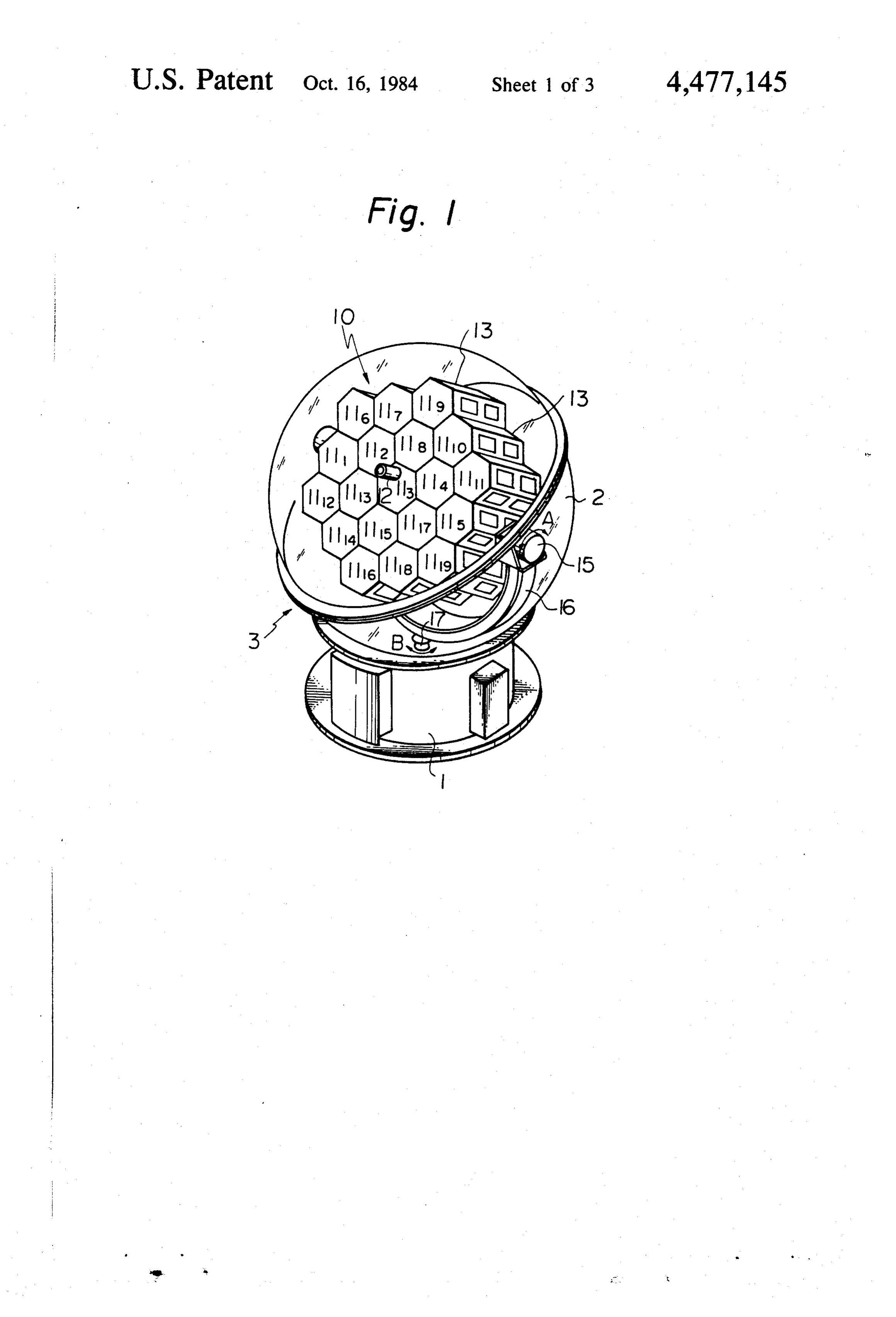
SUNLIGHT COLLECTING AND in both directions indicated by double arrow A; a sup CONCENTRATINGAPPARATUS port arm 16 for supporting the lenses 111, 112 . . . 1119, tracking sensor 12, holding frames 13, and first motors
BACKGROUND OF THE INVENTION 5 15; a rotatable shaft 17 disposed perpendicularly to a 1. Field of the Invention rotational axis of the first motors 15 as well as support The present invention relates to a sunlight collecting ing the support arm 16; and a second motor (not shown) and concentrating apparatus. More particularly, the for turning the rotatable shaft 17 in both directions present invention relates to a sunlight collecting and O indicated by double arrow B.
concentrating apparatus provided with a capsule en When the sun's azimuth and altitude are detected by closing lenses for collecting sunlight and a sensor for the tracking sensor 12, the first and second motors are detecting changes in the sun's azimuth and altitude. controlled by the output signals produced thereby so 2. Description of the Prior Art that the lenses 111, 112. . . 1119 can continuoulsy track In previous sunlight collecting and concentrating the movement of the sun. The sunlight collected by the apparatuses of this type, the temperature within the 5 lenses 111, 112... 1119 is introduced into optical conduc capsule is raised by the sunlight or lowered by the sur tor cables (not shown) or the like, 19 in number in the rounding cold air. example of FIG. 1, with inlet ends disposed at the focal Such sunlight collecting and concentrating appara positions of each of the lenses, and is propagated tuses have suffered from temperature-related break through the optical conductor cables to any place de downs and malfunctions of the sensor. To prevent such 20 sired, for example, to somewhere illumination is de breakdowns and malfunctions and also to prevent dete sired.
rioration of the sensitivity of the sensor, the air in the The sunlight collecting and concentrating means 10 is capsule must be controlled to a proper level. hermetically sealed in the transparent head member 2 to SUMMARY OF THE INVENTION 25 protect it from wind, rain, and dust. Therefore, the temperature within the head member 2 may considera
The present invention is intended to overcome this bly rise due to the sunlight or abnormally fall due to the defect of the prior technique. According to the present surrounding cold air. This exerts many harmful influ invention, there is provided a sunlight collecting and ences upon devices in the head member 2. In particular, concentrating apparatus wherein the temperature extreme temperature fluctuations hinder the ability of within the capsule can be maintained to a proper level. 30 the tracking sensor 12. This results in a lower collecting This prevents temperature-related breakdowns and efficiency of the apparatus.
malfunctions of the sensor and temperature-related de The present invention overcomes this defect by pro terioration of the sensitivity of the sensor. ducing an air current around the tracking sensorso as to BRIEF DESCRIPTION OF DRAWINGS 35 protect it from extremes of temperature and to keep the The invention will be more fully understood from the operation of the tracking sensor normally. Therefore, following detailed description taken in conjunction the sunlight collecting and concentrating apparatus can with the accompanying drawings, in which: continuously collect sunlight at a high efficiency. FIG. 1 is a general perspective view of the structure FIG. 2 is a side elevational view, partly in cross-sec of a previous sunlight collecting and concentrating tion, partly schematic, of an embodiment of the sunlight collecting an concentrating apparatus according to the apparatus of the type of the present invention,
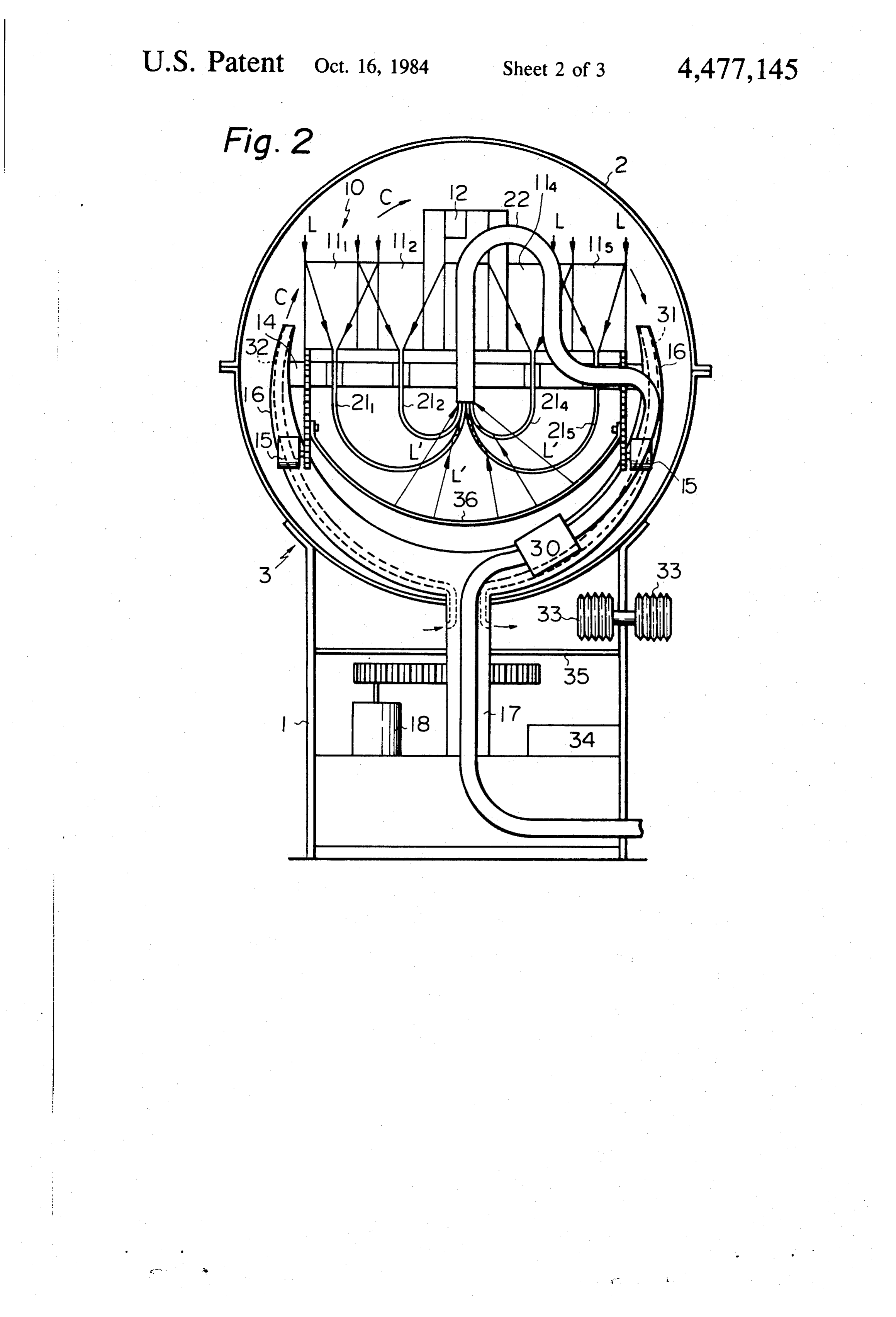
FIG. 2 is a side elevational view, partly in cross-sec present invention. Reference numeral 14 represents a tion partly schematic, of an embodiment of the sunlight first rotatable shaft driven by first motors 15. Reference collecting and concentrating apparatus according to the numeral 18 represents a second motor for driving a present invention; and 45 second rotatable shaft 17. Lenses 111, 112, 114, and 115 FIG. 3 is a pictorial rear view of the lens system of correspond to the lenses 111, 112, 114, and 11s shown in the embodiment shown in FIG. 2. FIG. 1. The sunlight L collected by these lenses 111 to 115 (no lens 113) is introduced into optical conductor
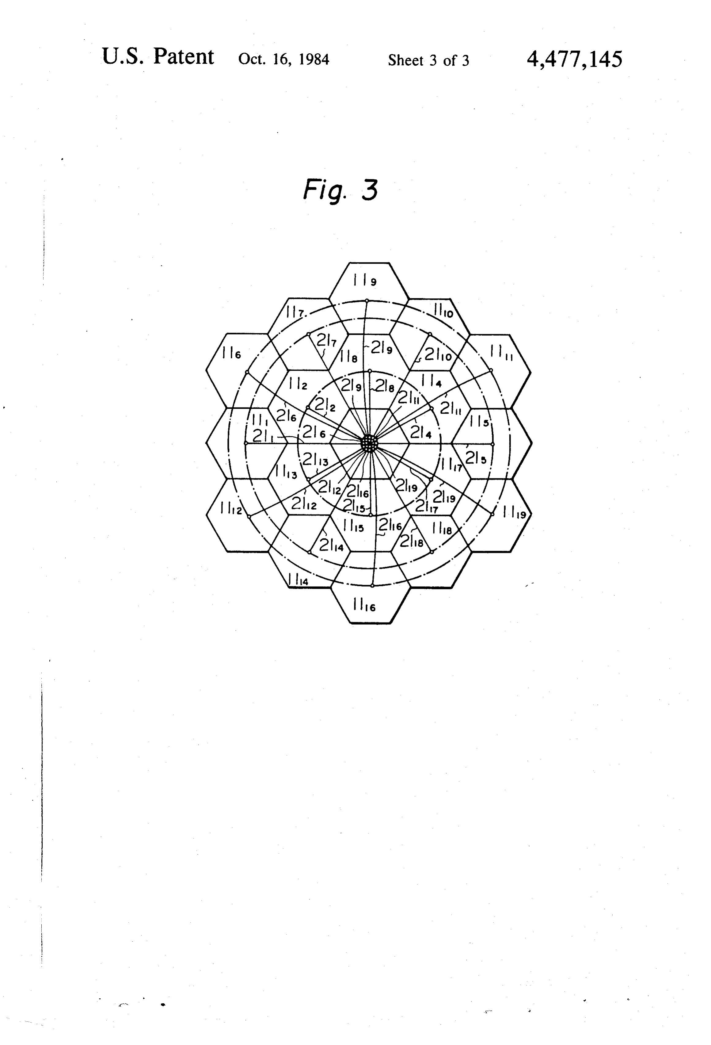
DESCRIPTION OF THE PREFERRED cables 211 to 215 (no cable 213) with inlet ends disposed EMBODIMENT SO at focal positions of each of the lenses. In the present FIG. 1 is a perspective view of a sunlight collecting invention, the area corresponding to the lens 113 shown and concentrating apparatus previously proposed by in FIG. 1 is occupied by a single major optical conduc the present inventor. tor cable 22. The single major optical conductor cable Referring to FIG. 1, there is shown a capsule 3 for a 22FIG. will be fully described later. 3 is a rear view of the lens system including a sunlight collecting and concentrating apparatus com 55 prised of hollow cylindrical base member 1 and trans plurality of such lenses. As shown in FIG. 3, 18 lenses parent head member 2 formed in the shape of a sphere the 111... 119 (no lens 113) are substantially arranged in or dome and mounted on base member 1. The head form of concentric circles with common axes. The member 2 has a sunlight collecting and concentrating inlet end of each of the optical conductor cables 211 . . means 10 enclosed therein. . 219 (no cable 213) is disposed at focal positions of each The sunlight collecting and concentrating means 10 of the lenses. The outlet ends of the optical conductor includes a plurality of lenses 111,112. . . 1119 (e.g., 19 in cables 211 to 2119 are gathered at the central portion of number) arranged substantially in the form of concen the lens system. The gathered optical conductor cables tric circles and integrally connected with each other for 65 are connected to a single major optical conductor cable collecting sunlight; a tracking sensor 12 for detecting 22 at the central portion. The sunlight is propagated the sun's azimuth and attitude; holding frames 13 inte through the single major optical conductor cable 22 to grally holding said lenses 111, 112... 1119 and the track any place desired, for example, to somewhere where ing sensor 12; first motors 15 for turning the lenses 111, illumination is desired.
Page 6scan →
As mentioned above, the sunlight collected by a plu In addition to the problem with sunlight not collected rality of lenses 111 to 1119 is introduced to the optical by the lenses, there is a problem with sunlight collected conductor cables 21 to 2119 disposed at respective by the lenses but not captured by the optical conductor lenses 111 to 1119. The outlet ends of the cables are cables. Furtheremore, the focal image of skylight is too gathered at the central portion of the lens system ar large to introduce into the optical conductor cables. ranged in the form of concentric circles. Finally, the Such sunlight and skylight are also transformed into gathered optical conductor cables are connected to the heat energy to raise the temperature within the head single major optical conductor cable 22 at the central member 2. To reduce such harmful influences, a collect portion, so as to convey the sunlight to any place de ing and reflecting plate 36 in the form of concave mirror sired. Therefore, distribution of the optical conductor 10 is provided within the head member 2. In FIG. 2, L', L' cables is considerably easy. For the optical guide, an ... represent light from the skylight which could not be optical conductor rod can be used in place of the optical captured by the optical conductor cables and were conductor cable. This results in low cost of the optical reflected by the plate 36. The collecting and reflecting conductor material. plate 36 is disposed at the rear side of the plurality of Even with the tracking sensor provided in the sun 15 lenses 111 . . . and the optical conductor cables 211 . . . light collecting and concentrating apparatus for detect and is integrally formed with the first rotatable shaft 14. ing the sun's azimuth and altitude and for enabling the On the other hand, outlet ends of the optical conduc lenses to continuously track the movement of the sun, it tor cales 211 . . . are gathered and connected to the is almost impossible for the lenses to collect all of the single major optical conductor cable 22 at the center sunlight incident with the head member enclosing the 20 position of the plurality of lenses 111... The gathered Sunlight collecting and concentrating means. Left to optical conductor cables 211 . . . are stripped of their itself, the sunlight would raise the temperature within cladding layers (not shown) at least at portions adjacent the head member and exert a harmful influence upon to the central position. Thus, reflected light L', L' . . . the apparatus, in particular upon the tracking sensor. As are completely captured into outlet ends of the respec shown in FIG. 2, when the axis of the lenses is directed 25 tive optical conductor cables 211, 212, 214, 215. . . , then to the meridian sun, the tracking sensor is positioned at of the single major optical conductor cable 22. This the apex point whithin the capsule. In such a case, the further prevents extreme temperature rises within the temperature at the apex point is raised considerably. head member 2, and allows a further increase of the Reference numerals 31 and 32, are air supply passages collecting efficiency of the apparatus. formed inside the support arm 16. One end of each these 30 In this embodiment, the suction pump 30 is provided passages 31 and 32 is opened within the head member 2. on the passage 31. It will be noted, however, that the Each other end is opened within the base member 1. On present invention is not limited to this embodiment. the passage 31, there is provided a suction pump 30. Instead of the suction pump 30, a blower or both a Reference numeral 33 denotes a heat exchanger pro suction pump and blower may be provided on the pas vided within the base member 1. 35 sage 31.
When the air within the head member 2 is heated by Also in this embodiment, the passages 31, 32 are the sunlight incident therethrough, the suction pump 30 formed inside the support arm 16, and the tracking operates to introduce the hot air from the head member sensor 12 is provided at the center of the lens system. 2 into the base member 1 through the passage 31 formed However, the passages do not necessarily have to be inside the support arm 16. Then, the introduced hot air inside the support arm, also the tracking sensor does not is cooled by the heat exchanger 33 provided within the always have to be provided at the center of the lens base member 1. The cooled air is returned from the base system.
member 1 into the head member 2 through the passage Generation of the air current may be effected contin 32 formed inside the support arm 16, this operation is uously or intermittantly. Furthermore, a temperature caused by the vacuum produced around the tracking 45 sensitive sensor may be provided within the head mem sensor 12. At that time, as shown by arrow C in FIG. 2, ber 2 advantageously, adjacent to the tracking sensor the cooled air passed through the passage 32 will be 12, so as to generate the air current only when the tem blown against the tracking sensor 12. perature within the head member differs from the pre The above produces a strong air current in the region determined level.
of the tracking sensor 12 and disperses the hot air there 50 When the tracking sensor is provided at the central around, preventing an unwanted rise of the air tempera portion of the lens system and when the axis of the lens ture around the tracking sensor 12. As already de system is directed to the meridian sun, the temperature scribed, the dispersed hot air is introduced into the base around the tracking sensor will reach its highest degree, member 1, within which the air is cooled by the heat i.e., at midday, the tracking sensor will most approach exchanger 33. Accordingly, the air temperature around 55 the apex within the capsule, which has the highest tem the tracking sensor 12 can be maintained at a predeter perature. To detecting when the axis of the lens system mined level. is closest to the meridian sun and start the air current Within the base member 1, a control circuit 34 is blowing against the tracking sensor, a microswitch or provided. The control circuit 34 operates, as is well the like may be provided on the first or second rotatable known, to receive signals indicating the sun's azimuth shafts.
and altitude from the tracking sensor 12 and to control The above-mentioned embodiment was mainly de the motors 15 and 18 for driving the apparatus to pre scribed in reference to air cooling within the head mem cisely track the movement of the sun. If the hot air ber. However, it can readily be understood that the heat supplied through the passage 31 were to blow against energy can be positively extracted from the head mem the control circuit 34, this would cause circuit malfunc 65 ber both for lowering of the temperature therein and tions. The present invention overcomes this defect by utilization for other purposes. Further, if the tempera providing a partition 35 dividing the space of the base ture of the ambient air surrounding the head member is member 1 into two compartments. very low, the temperature therein becomes abnormally 7 low, which may also cause breakdowns and malfunc 5. The sunlight collecting and concentrating appara tions of the tracking sensor 12. In such a case, heat tus as claimed in claim 4, in which said air current be energy from an outside heat source (not-shown) may be gins to be produced around said sensor means when the supplied through the passages 31, 32 and heat exchanger axis of the lens means is directed to a meridian sun. 33 into the head member to maintain the temperature at 6. The sunlight collecting and concentrating appara the proper level. tus as claimed in claim 1, in which the suction pump or As can readily understood from the above, according blower is provided on said support arm to effect the air to the present invention, the temperature within the current around the sensor means through passages head member, particularly, extremes of temperature formed inside the support arm.
around the tracking sensor, may be effectively con 10 7. The sunlight collecting and concentrating appara trolled so as to prevent breakdowns and malfunctions. tus as claimed in claim 1, in which said capsule com Thus, the efficiency of the apparatus can be increased. prises a transparent head member formed in the shape of Furthermore, according to the special arrangement sphere for enclosing a sunlight collecting and concen of the optical conductor cables and the collecting and trating means and a base member for supporting the reflecting plate of the present invention, the sunlight 15 head member, said base member being provided with a collected by the lens system may be efficiently intro heat exchanger, whereby the air within the head mem duce into the optical conductor cables. ber may be cooled or heated within the base member The invention has been described in detail with refer and be returned again into the head member. ence to preferred embodiments thereof, but it will be 8. The sunlight collecting and concentrating appara undertstood that reasonable variations and modifica 20 tus as claimed in claim 7, in which said base member is tions are possible without departing from the spirit and provided with an isolated compartment for receiving scope of the invention. said heat exchanger, so as to effect heat exchanging I claim between said compartment and the ambient air. 1. A sunlight collecting and concentrating apparatus 9. In a sunlight collecting and concentrating appara comprising: 25 tus comprising:
a lens means for collecting sunlight; a plurality of lenses for collecting sunlight; a sensor means for detecting the sun's azimuth and a tracking sensor for detecting the sun's azimuth and altitude; altitude;
an optical conductor means to which the sunlight. a plurality of optical conductor cables oppositely collected by said lens means is introduced; disposed to respective lenses, into which the sun a first rotatable shaft for turnably supporting said lens 30 light collected by the lenses are introduced; means together with integrally constructed means a single major optical conductor cable connected to thereto; said plurality of optical cables, into which the sun a support arm for turnably supporting said first rotat light conveyed through said plurality of optical able shaft; conductor cables is introduced; a second rotatable shaft for turnably supporting said 35 a first rotatable shaft for turnably supporting lenses support arm about an axis perpendicular to the axis together with the integrally constructed members of said first rotatable shaft; and thereto;
a capsule, in which all of the above are hermetically a support arm for turnably supporting said first rotat sealed; wherein when the sun's azimuth and alti able shaft;
tude are detected by said sensor means, the turning a second rotatable shaft for turnably supporting said of said first and second rotatable shafts is con support arm about an axis perpendicular to the axis trolled to cause said lens means to face the position of said first rotatable shaft; and of the sun so as to introduce the collected sunlight a transparent capsule, in which all of the above are by said lens means into said optical conductor 45 wherein hermetically sealed;
when the sun'azimuth and altitude are de means; characterized in that: tected by said tracking sensor, the turning of said a suction pump or blower is provided within said first and second rotatable shafts is controlled to capsule so as to produce an air current around said cause lenses to face the position of the sun so as to sensor means, and to effectively maintain the tem-. introduce the collected sunlight by said lenses into perature around the sensor means to a proper level. 50 said optical conductor cables; the improvment 2. The sunlight collecting and concentrating appara comprising:
tus as claimed in claim 1, in which said lens means com at the rear side of the space formed by the plurality of prises a plurality of lenses substantially arranged in the lenses and optical conductor cables, a collecting form of concentric circles, and in which said optical and reflecting plate integrally turnable with said conductor means comprises a plurality of optical con first rotatable shaft is provided and, substantially at ductor cables, the inlet end of said cables disposed at the 55 the central position of the concentric circles focal positions of each of the lenses and the outlet ends formed by the plurality of lenses, the outlet ends of connected to a single major optical conductor cable said optical conductor cables are connected to said provided coaxially through the inside of the first rotat single major optical conductor cable with its inlet able shaft. end facing to the reflecting surface of said collect 3. The sunlight collecting and concentrating appara ing and reflecting plate; said optical conductor tus as claimed in claim 2, in which said single major cables being stripped of their cladding layers at optical conductor cable is provided through the support least at portions adjacent to said central position, so arm and coaxially through the inside of the second as to introduce uncaptured light at the inlet ends of rotatable shaft. the optical conductor cables into said cables 4. The sunlight collecting and concentrating appara 65 through the collecting and reflecting plate and to tus as claimed in claim 2, in which said sensor means is effectively maintain the temperature around the disposed substantially at the central portion of the con tracking sensor to a proper level. centric circles formed by the plurality of lenses. k is k
Page 8scan →
-- --- t. in -
— '' ' - r ,, , -
UNITED STATES PATENT ANL , al......... . . 477 - 14 ,
Certificate of correction
INVENTO R(S) : Kei Mori
It is certified that error appears in the above-identified patent and that said Letters Patent is hereby Corrected as shown below:
Column 2 r line l3, "continuoulsy" should be --continuously--; Column 2, line 20, after "somewhere" insert --where--;
Column 3 lines 27, "whithin" should be --within--
Column 3, line 30, after "each" insert --of--
Column 4, line l8, "Cales" should be --cables--;
Column 4, line 44, "intermittantly" should be "intermittently--; Column 4, line 56, "detecting" should be --detect--;
Column 5 line 7, after "can" insert --be--
Column 5, lines, l0-17, "introduce" should be -- introduced--; Column 6, line 45, "sun" azimuth" should be -- sun's azimuth--.
eigned and Sealed this
Twenty-fifth Day of June 1985
Seal)
Attest:
Donald j. quigg
Attesting Officer Acting Commissioner of Patents and Trademarks
Page 9scan →
United states patent and trademark office
Certificate of correction
NVENTOR(S) : Kei Mori
It is Certified that error appears in the above-identified patent and that said Letters Patent is hereby corrected as shown below:
Column 2 r line l3, "Continuoulsy" should be --continuously--; Column 2, line 20, after "somewhere" insert -- where--; Column 3 lines 27, "whithin" should be -- within-- Column 3, line 30, after "each" insert --of--
Column 4 line l8, "Cales" should be -- cables--
Column 4, line 44, "intermittantly" should be "intermittently-- Column 4, line 56, "detecting" should be --detect-- Column 5, line 7, after "can" insert --be--
Column 5, lines l6-17, "introduce" should be -- introduced-- Column 6, line 45, "Sun" azimuth" should be -- sun's azimuth--.
eigned and Sealed this
Twenty-fifth D 2 y O f June 1985
Seal
Attest:
Donaldj. quigg
Attesting Officer Acting Commissioner of Patents and Trademarks
Provenance
- Collection
- Patents citing this work
- Pages
- 9
- Method
- pdftotext (the PDF's own text layer) + pdftoppm 300dpi page scans
- Patent office record
- patents.google.com →
- Source
- Google Patents citing-documents table
- Assignee
- Kei Mori
- Published
- 1984-10-16
- Transcribed from
- patentimages.storage.googleapis.com →