

patent · US4528978A
Solar rocket absorber
16 July 1985
Text
Page 1bibliographic recordscan →
United States Patent (19) Patent Number: 4,528,978 Robinson (45) Date of Patent: Jul. 16, 1985 (54) SOLAR ROCKET ABSORBER FOREIGN PATENT DOCUMENTS Inventor: Philip I, Robinson, Calabasas, Calif. 2833098 2/ 1980 Fed. Rep. of Germany ...... 26/442 (73) Assignee: The United States of America as 1179202 5/1959 France ................................ 26/440 represented by the Secretary of the
Air Force, Washington, D.C. OTHER PUBLICATIONS (21) Appl. No.: 559,169 "Development of a Solar Receiver for an Organic Ran kine Cycle Engine', Conference: Proceedings of the (22 Filed: Dec. 8, 1983 16th Intersociety Energy Conversion Engineering Con Int. Cli................................................. F24J 3/02 ference, Technologies for the Transition, Atlanta, GA. 52 U.S. Cl. .......... ... 126/438; 126/441; (Aug. 9, 1981), pp. 1764-1769. 126/442; 126/450; 60/203.1; 60/641.8; Gov. Contract Report RTD-TDR-63-1085, "Research 60/641.15; 165/163 and Development Studies to Determine Feasibility of a 58 Field of Search ............... 126/438, 440, 44, 442, Solar LH2 Rocket Propulsion System", by Electro-Op 126/448, 450; 60/203.1, 641.8, 641.13, 641.14, tical Systems, Inc., Pasadena, CA, pp. 157-219, Sep.
(56) References Cited Primary Examiner-Margaret A. Focarino
Attorney, Agent, or Firm-Donald J. Singer; Stanton E.
Collier 1,951,403 3/1934 Goddard ............................. 26/27 57 ABSTRACT 3,064,418 11/1962 Sanders ................................... 60/26 3,153,279 10/1964 Chessin. ... 29/420 A solar rocket absorber of rhenium tubes is used to 3,203,167 8/1965. Green ...................................... 60/26 provide heated liquid hydrogen to a thruster. The rhe 3,903,700 9/1975 Glickman... ... 60/641 nium tubes are wrapped in a closed shape having an 3,927,659 12/1975 Blake et al..... . 126/271 opening for receiving solar radiation for heating the 3,968,652 7/1976 Chevalier ....... ... 60/641 3,998,205 12/1976 Scragget al... 26/27 liquid propellant. The vessel of rhenium tubes is held by 4,029,077 6/1977 Gorniak .............................. 126/440 a carbon shell which is further encased in a reradiation 4,036,012 7/1977 Monsler. ... 60/203 shield to prevent heat loss.
4,258,698 3/1981 Sales. . 126/440 4,354,348 10/1982 Lee ..................................... 60/203.1 10 Claims, 2 Drawing Figures
CARBON RINGS,32
CONCENTRAT g
RERADATION SHIELD,34
Drawings
Page 2drawing sheetscan →
Page 3scan →
pleted, the tubes are again bent at 90 degrees and a disk,
SOLAR ROCKETABSORBER the top of the hat, is wound to complete the hat shape.
Statement of government interest
The disk is also tightly wound as the brim leaving no space between the coils. The tubes at the center of the
The invention described herein may be manufactured 5 disk reverse direction and wind back up the disk and and used by or for the Government for governmental cylindrical vessel and exit next to the top disk. The purposes without the payment of any royalty thereon. absorber is housed in a graphite shell to provide struc BACKGROUND OF THE INVENTION tural support. The inner surface of the shell has splines 10 into which is machined a helical groove. The pitch of
The present invention relates generally to rocket the groove and the rhenium cylindrical coils are the motors, and, in particular, relates to an absorber for use same so that the coils can be threaded into the graphite in outer space that heats a liquid by solar energy and shell. The groove in the splines locates the coils one-half outputs the heated fluid to a thruster. -tube radius away from the shell which allows the back Satellites parked in a stationary orbit need thrusters to 15 side of the coils to absorb reflected radiation. The coils correct and maintain a position in orbit; otherwise, also tends to reduce re-radiation losses from the cavity eventually, the satellite will drift out of the desired position and thus become useless. Once the satellite is by physically blocking a portion of the re-radiation. The graphite shell in both designs will be coated with a correctly positioned, thrusters having a small specific CVD refractory impulse can be turned on and off to maintain the proper 20 of carbon into thecarbide coating to stop the migration rhenium coils.
stationary orbit. Although this use of thrusters is clear, other uses are also needed where a low specific impulse provide for an absorber thatofutilizes It is, therefore, one object the present invention to a coiled tube de is sufficient.
One thruster uses a liquid propellant and an oxidizer Sign;
that are combined in the thrust chamber. Ignition oc It is another object of the present invention to pro vide for an absorber that is simple in design and of low curs upon contact. This thruster requires storage of two 25 weight;
liquids, piping for both and pumps. and
Another thruster uses a liquid propellant that is It is a further object of the present invention to pro heated to a high degree by an internal source. This type vide for an absorber that can be fabricated easily. of thruster is heavier and requires constant standby These and many other objects, features, and advan energy to maintain the heat source in a ready state. 30 tages of the present invention will be readily apparent to Another type of thruster uses an external source of one skilled in the pertinent art from the following de heat, i.e., the sun, to heat the liquid propellant to a high tailed description of a preferred embodiment of the degree for expansion. Previous designs of absorbers, the invention and related drawings when considered in device to super heat the liquid propellant, were compli conjunction with the claims.
cated, difficult to manufacture, and inefficient. 35
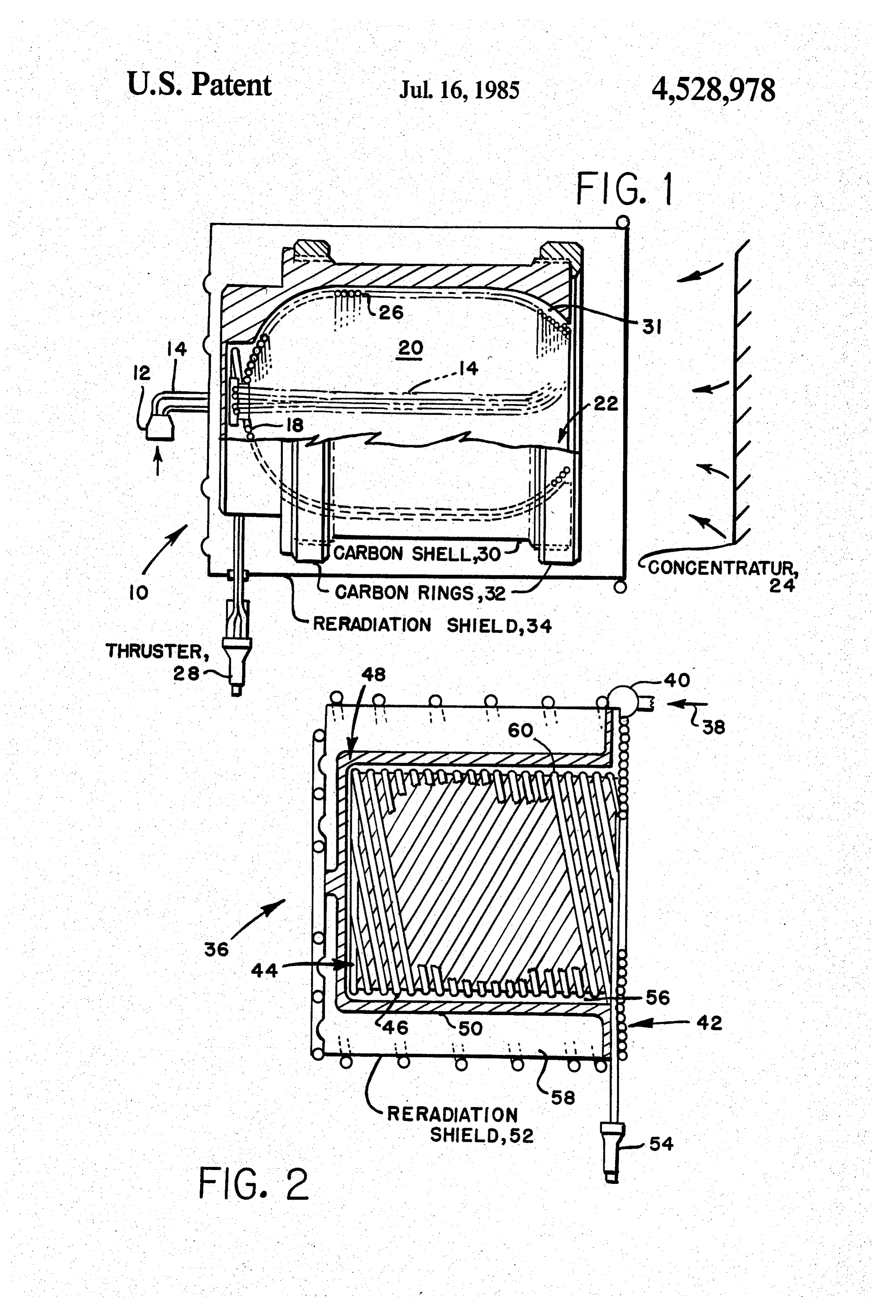
The above problems have motivated a search for a BRIEF DESCRIPTION OF THE DRAWINGS solar absorber for minimizing weight, manufacturing FIG. 1 is a cross-section of the absorber of this inven problems, and other inefficiencies. tion. --
SUMMARY OF THE INVENTION FIG. 2 is a cross-section of the alternative absorber of this invention.
The present invention sets forth an absorber and thereby overcomes the problems set forth hereinabove. DETALED DESCRIPTION OF THE A four-coiled rhenium tube absorber is formed in the PREFERRED EMBODIMENT shape of a cylindrical pressure vessel with hemispheri One of the keys to a high performance solar thermal cal tops. Orie of the tops is truncated to make a circular 45 rocket is an absorber opening. The vessel wall is formed by four, circumfer efficient so that there10,canshown be a in FIG. 1, that is highly reduction in the space entially wound parallel tubes. At the opening, the tubes enter the vessel tangentially to the opening, and as the craft collector size and weight as well as other compo tubes approach the closed end, the tubes are wound nents in the system.
around increasingly smaller circumferences until the 50 thrust for absorber
A high efficiency results in the maximum a fixed final propellant temperature and a minimum allowable bend radius is reached. The remain ing hole is filled with a graphite plug which has the given solar concentrator. To achieve high propellant temperatures effectively, the absorber reflected and input tubes routed through the plug to provide the re-radiation losses must be minimized. These losses are necessary cooling. The vessel is placed in a shell to provide structural support and a radiation shield is 55 strongly influenced by the absorber configuration, ma added to protect against heat loss. terials selected, absorber cooling, and radiation shield A double-coiled rhenium tube absorber is shaped like ing.
an inverted top hat. Two parallel rhenium input tubes A study of available materials indicated that rhenium are wound to form the "brim' or disk of the absorber. is the most promising material because of weldability, The tubes enter at the outer edge of the brim tangen refactory abilities, and ductility. Rhenium tubes, for tially and are connected to a hydrogen inlet manifold. example, 0.117 inches OD and a wall thickness of 0.010 The tubes are wound tightly enough to form a continu inches, are made by the chemical vapor deposition pro ous brim to provide a solid barrier to the incident solar cess. Currently, the tubes are available in four foot radiation. From the inner edge of the brim, the tubes are lengths. Because of the ease of welding rhenium, a tube bent at 90 degrees to the brim and winding is continued 65 of any desired length can be obtained by welding multi to form a cylindrical vessel of the absorber. The tubes ple four foot lengths together. Welded joints will be are wound in the shape of a loose helix allowing space made with a to inch sleeve fitted over the tube junc to remain between each coil. Once the vessel is com tion. The sleeve will be electron beam (EB) welded to 4 each of the tubes. The thruster will also be EB welded 46. Once vessel 44 is completed, tubes 38 are again bent to the tubes as needed. at 90 degrees and a disk 48 is wound at the top of the Referring to FIG. 1, a cylindrical shaped absorber 10 hat-shaped absorber 36. Disk 48 is tightly wound leav is shown in cross-section. Upon command, the liquid ing no space between tubes 38. Tubes 38 reverse direc hydrogen, for example, stored in a container, not tion of winding in disk 48 and wind back on vessel 44 shown, is allowed to flow into an input coupling 12 by and exit near brin 42 to connect to a thruster 54. a control valve, not shown. Absorber 36 is housed in a graphite shell 50 to pro The liquid hydrogen enters in a group of four parallel vide structural support. The inner surface of shell 50 has tubes 14 that enter a graphite plug 16 that fills a rear a plurality of splines 56 into which is machined a helical opening 18. The liquid hydrogen that passes there 10 groove 60. The pitch of groove 60 and rhenium coils 46 through cools plug 16 from solar radiation. From plug are the same. Groove 60 in splines 56 locate coils 46 16, tubes 14 are routed to a front opening 22 after tra one-half tube radius from shell 50 which allows the versing the outside of a wall 26 and are there bent to backside of coils 46 to absorb reflected radiation. Coils form opening 22 that allows solar radiation to enter a 46 tend also to reduce re-radiation losses from vessel 44 vessel 20 from a solar concentrator 24. Tubes 14 are 15 by physically blocking a portion of the re-radiation. In bent in a cylindrical fashion to form wall 26 of vessel 20. order to maintain heat within shell 50, a re-radiation Vessel 20 is bottle shaped with rear and front openings shield 58 is positioned about carbon shell 50 and is cylin 18 and 22 having a diameter smaller than vessel 20. drical shaped. As in the case of absorber 10 having four When the radius of curvature becomes too small for parallel tubes 14, shell 50 would be coated with a CVD bending tubes 14, this defines the diameter of rear open 20 refractory carbide coating.
ing 18. Tubes 14 are then joined by welding to a thruster Clearly, many modifications and variations of the 28. A carbon shell 30, being in split halves, fixedly holds present invention are possible in light of the above vessel 20 with a plurality of splines 31, only one is teachings and it is therefore understood, that within the shown. Splines 31 run traversely with respect to vessel inventive scope of the inventive concept, the invention 20. Carbon rings 32 hold carbon shell 30 together. In 25 may be practiced otherwise than specifically claimed. order to maintain heat within shell 30, a re-radiation Table I shows the advantages and disadvantages of shield 34 is positioned about carbon shell 30 and allows the two designs.
Table
Typical, heat exchanger cavity test hardward design comparison
Design design features advantages disadvantages
Coiled Rhenium Tubes "Rhenium Tube *Closed-Coiled "Requires Radiation --- FOUR-TUBE Cavity Tube Winding Shield "Carbon Composite Provides Sturdy "Uses High Cost or Graphite Construction Material
Jacket *Fabrication is "High Weight within the State of the Art
Coiled Rhenium Tube *Open Coiled "Simple Design "Requires
TWO-TUBE Rhenium Tube- "Fabrication Ease Radiation
Graphite Cylinder "Low Weight Shield
Cavity Full utilization *Uses High Cost of Coit surface Material
Area (Reduction "Possible
Free to Grow Loss from from Thermal External
Loading Surfaces
Uses Less Tube
Material the liquid hydrogen to flow into and out by means of tubes 14.
An input coupling 12 can be platinium brazed to tubes 50 14 since the temperature at that point should remain What is claimed is:
below 2500 R and thus amenable to platinum brazing. 1. A solar rocket absorber, said absorber receiving Thruster 28 can be formed by chemical vapor deposi solar radiation to heat a liquid propellant passed there tion and welded to tubes 14. through and output through a thruster, said absorber If carbon infiltration causes rhenium tubes 14 to 55 comprising:
weaken, a coating of CVD tungsten can be applied to a vessel, said vessel being shaped as a cylindrical-tube shell 30. The tungsten and carbon would react to form with a pair of hemispherical tops, each of said tops tungsten carbide and thus prevent carbon infiltration having a concentric opening therein, said vessel into the rhenium. being formed by parallel tubes having said liquid Referring to FIG. 2, an alternate absorber 36 is 60 propellant therein, said tubes having an input cou shown. A pair of parallel tubes 38 enter at an input pling attached to an input end and a thruster at coupling 40 from which they spiral inward to form a tached to an output end, one of said concentric brim 42 of absorber 36. Tubes 38 can be wound tightly openings being a front opening for receiving solar enough to form continuous brim 42 to provide a solid radiation, and the other of said concentric openings barrier to the incident solar radiation. Tubes 38 exit 65 being a rear opening;
brim 42 at a 90 degree angle and wind to form a cylin a plug positioned in said rear opening to block the drical vessel 44. Tubes 38 are wound in the shape of a transmission of solar radiation therefrom, said plug loose helix allowing space to remain between each coil being cooled by liquid propellant in said tubes;
Page 5scan →
a shell for holding said vessel, said shell having a through and output through a thruster, said absorber cavity therein closely conforming to the shape of comprising:
said vessel, said shell having a first opening to a vessel, said vessel being shaped as a top hat, said allow solar radiation to enter said front opening of vessel being formed by parallel tubes having said said vessel, said cavity having a plurality of splines liquid propellant therein, said tubes being in close contact to form a brim of said vessel, said tubes thereon to hold off said vessel, said shell being exiting said brim at a 90 degree angle and thereafter separable for purposes of inserting said vessel being loosely coiled to form a cylinder, said tubes therein, said shell having rings circumferentially again being bent at a 90 degree angle and thereafter attached about said shell to fixedly hold said shell 10 forming a disk, said tubes reversing direction in together; and said disk and winding back on said vessel to exit a reradiation shield positioned about said shell to rear said brim;
prevent the transmission of heat from said shell. a shell having splines in a cavity for holding said vessel, said splines fixedly holding said vessel away 2. A solar rocket absorber as defined in claim 1 is from said shell; and wherein said tubes are parallel groups of four wrapped a reradiation shield positioned about said shell. to form said vessel. 7. A solar rocket absorber as defined in claim 6 3. A solar rocket absorber as defined in claim 2 wherein said tubes are a parallel group of two wrapped wherein said tubes are made of rhenium. to form said vessel.
4. A solar rocket absorber as defined in claim 320 8. A solar rocket absorber as defined in claim 7 wherein said shell is made of carbon. wherein said tubes are made of rhenium. 5. A solar rocket absorber as defined in claim 4 9. A solar rocket absorber as defined in claim 8 wherein said shell is made of carbon.
wherein said shell has a CVD refracting carbide coating 10. A solar rocket absorber as defined in claim 9 to prevent the migration of carbon to said rhenium. 25 wherein said shell has a CVD refracting carbide coating 6. A solar rocket absorber, said absorber receiving to prevent the migration of carbon to said rhenium. solar radiation to heat a liquid propellant passed there k . . . . .e :
Provenance
- Collection
- Patents citing this work
- Pages
- 5
- Method
- pdftotext (the PDF's own text layer) + pdftoppm 300dpi page scans
- Patent office record
- patents.google.com →
- Source
- Google Patents citing-documents table
- Assignee
- The United States Of America As Represented By The Secretary Of The Air Force
- Published
- 1985-07-16
- Transcribed from
- patentimages.storage.googleapis.com →