

patent · US4541415A
Solar ray collecting device
17 September 1985
Text
Page 1bibliographic recordscan →
United States Patent (19)
Mori
54). SOLAR RAY COLLECTING DEVICE
76 Inventor: Setagaya-ku, Tokyo, Japan
30 Foreign Application Priority Data
Jun. 3, 1983 JP Japan .................................. 58-99978 Int. Cl. ............................ F24J 3/02; G02B 7/02 52 U.S.C. ..................................... 126/440; 350/253
4,026,267 5/1977 Coleman ............................. 126/440 4,057,048 11/1977 Maine .................................. 126/440 4,334,522 6/1982 Dukess ................................ 126/418 4,354,348 10/1982 Lee ...................................... 126/440 Primary Examiner-William E. Lyddane
Assistant Examiner-Gerald A. Anderson
Attorney, Agent, or Firm-Jordan and Hamburg
A solar ray collecting device is comprised of a support ing base plate on which a large number of hexagonal recesses are provided and a large number of optical systems are arranged on each of said recesses. Each of said optical systems is made up of a hexagonal focusing lens of a dimension that is approximately the same as the hexagonal recesses and of a head-cut hexagonal pyramid which extends downward from the light col lecting lens as an upper surface of said recess. An opti cal conductor which is a light-receiving surface is pro vided on the focus of said light collecting lens. Further more, the upper internal circumferential surface of the side wall forming said recess is so formed that it may be able to move freely on the surface of said hexagonal pyramid.
16 Claims, 2 Drawing Figures
Drawings
Page 2drawing sheetscan →
Page 3scan →
on the focus of the light collecting lense. Furthermore,
SOLAR RAY COLLECTING DEVICE the upper internal circumferential surface of the side wall forming the recess is so formed that it may be able
BACKGROUND OF THE INVENTION to move freely on the surface of the hexagonal pyramid. This invention relates to a solar ray collecting device. 5 The above and other features and advantages of the It has been previously proposed that various solar ray present invention will become apparent from the fol collecting devices be used in which the solar rays fo lowing detailed description which goes with the accom cused by a lense or the like are guided into an optical panying drawings.
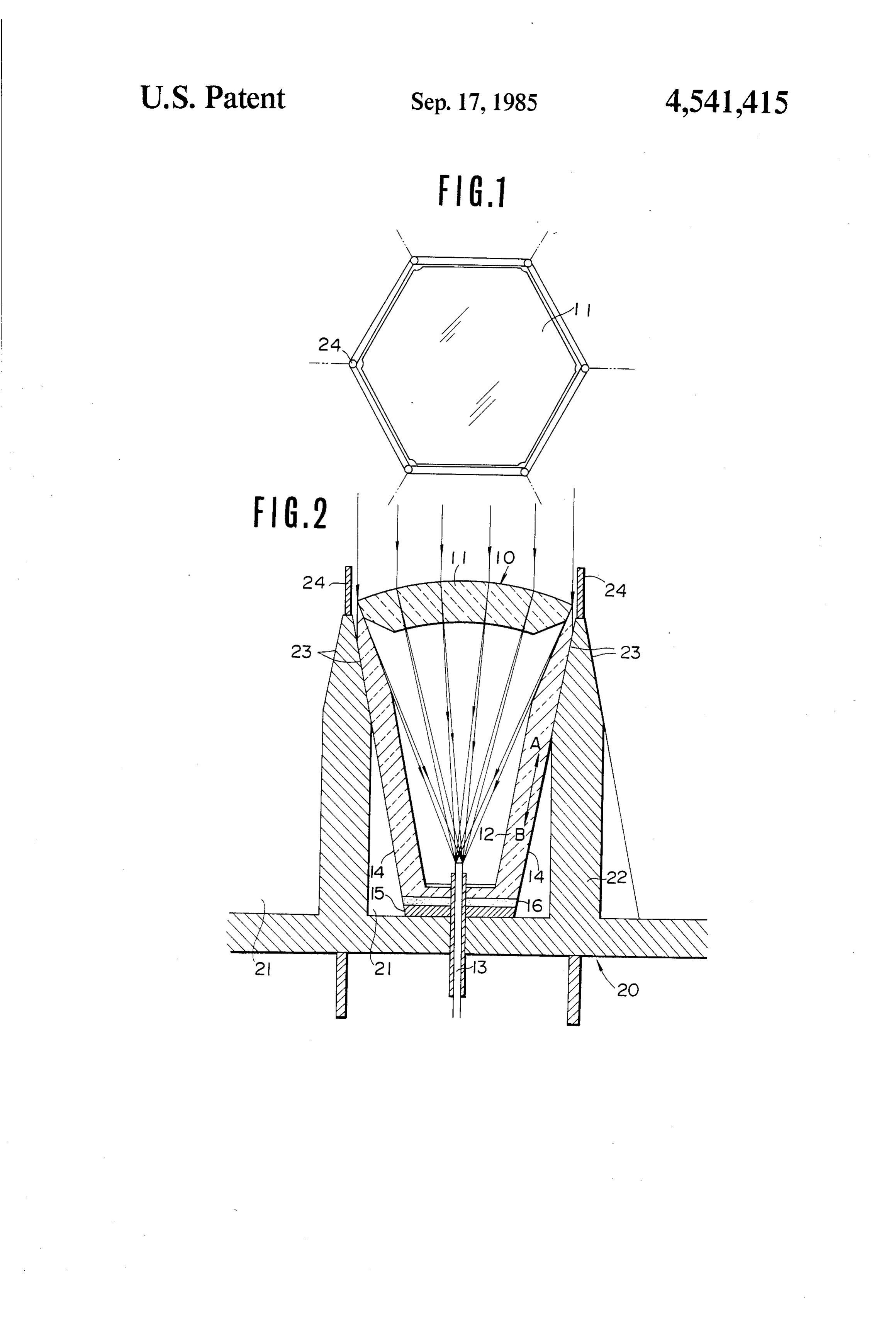
conductor cable and transmitted onto an optional de BRIEF DESCRIPTION OF THE DRAWINGS sired place for the purpose of illumination or for other 10 uses. One of the main solar ray collecting devices is the FIG. 1 is a plane view partly enlarged for explaining one in which a plurality of Fresnel lenses of approxi an embodiment of the present invention. mately 40 cm in diameter (for example 7, 19, or 37 Fres FIG. 2 is a cross-section view of FIG. 1. nel lenses of the same diameter) are used for collecting 15 DESCRIPTION OF THE PREFERRED solar rays on the light-receiving edge surface of an EMBODIMENTS optical conductor cable of about 1 cm in diameter. It is then mounted at the focus of the Fresnel lenses and the FIG. 1 is a plane view partly enlarged for illustrating solar rays focused by the Fresnel lenses are guided into the components of the present invention. FIG. 2 is a the optical conductor cable and transmitted to the op cross-sectional view of FIG. 1.
tional desired place through it. Another type of solar 20 In FIG. 1, 10 is an optical system, and 20 is its sup ray collecting device is one in which a large number of porting member. In practice, a large number of optical lenses, of less than about 4 cm in diameter, (for example systems (for example, 2,000 of them) are arranged on a 2,000 lenses of the same diameter) are used for collect supporting member 20. Basically each optical system 10 ing solar rays on the light-receiving edge of an optical is composed of a hexagonal lense 11 of about 4 cm or fiber having a diameter of about 0.1 to 0.2 mm. These 25 less in diameter; a head-cut hexagonal pyramid 12, the are precisely positioned at the focus of each lense, and upper surface of which is the lense 11; and an optical the solar rays focused by each lense are then guided into fiber 13, the light-receiving edge surface of which is them. The focal length of the lense is about 40 cm in the precisely positioned at the focus of the lense 11. The case of the former device while its focal length is about solar ray focused by the lense 11 is guided into the 4 cm or less in the case of the latter. Consequently the 30 optical fiber 13. A large number of hexagonal recesses value of the latter is that it makes it possible to create a 21 for accommodating the optical systems 10 are pro very thin solar ray collecting device. On the contrary vided on the supporting member. The upper portion of there exist drawbacks in that the focus position of the the side wall 22 forming the recess 21 is formed as an lense needs to coincide precisely with the light-receiv inclined ing edge surface, and as a result the lense and its sup 35 surface ofwall the having the same slant as the pyramidal hexagonal pyramid 12. When the lense porting member tend to expand due to the extreme heat. and the lense supporting member expand due to ambient This is especially true if the device is used in a desert, in heat, the hexagonal pyramid space, or in a tropical area where the ambient tempera rises, sliding along with the 12 of the optical system 10 inclined surface 23 in the ture varies to a great extent. As a result the positional direction shown by the arrow at A. On relationship between the focus position of the lense and 40 when they contract, the pyramid 12 sinks the contrary, sliding along the light-receiving edge surface of the optical fiber largely deviates from its predetermined relationship, in the direction as shown by an arrow at B. On that and consequently the lense and its supporting member occasion the focal position of the lense 11 does not are apt to be destroyed by the extreme heat. change at all, and therefore the solar rays are always 45 efficiently guided into the optical fiber 13. However, if
SUMMARY OF THE INVENTION the heat expansion rate of the lense is too great, there is It is therefore an object of the present invention to a possibility that the neighboring lenses will collide with provide a solar ray collecting device of the type in each other and will be destroyed. Supposing that a which a large number of lenses of about 4 cm or less in protection bar 24 is mounted on the top of the upper diameter are used to focus solar rays. It is another ob 50 surface of the side wall 22, namely the place where the ject of the present invention to provide a solar ray col lenses are most probably apt to be destroyed, each lense lecting device for effectively absorbing heat expansion will then collide with the protection bar first and this of the lense and its supporting member in order to pre area of the lense will only partially be destroyed. Conse vent them from being destroyed by extreme heat. An quently it may be possible to prevent the lenses from other object of the present invention is to provide a 55 being entirely destroyed by colliding with the sides of solar ray collecting device for enabling the focus posi the neighboring lenses. The solar rays focused by the tion of each lense to always coincide with the light lense 11 and guided into the optical fiber 13 is a direct receiving edge surface of the optical fiber. light beam delivered from the sun. On the other hand, A solar ray collecting device for enabling the focus an indirect light beam from the sun cannot be guided position of a lense to always coincide with an optical 60 into the optical fiber. If such an indirect light is utilized fiber is made up of a supporting base plate on which a it may be possible to suppress the heat expansion of the large number of optical systems are arranged. Each of spectrum system. For this purpose transparent acrylic the optical systems also has a hexagonal focusing lense material hardened at high temperatures is used in the of a dimension that is approximately the same as the hexagonal pyramid 12 and aluminum evaporation is hexagonal recesses; a head-cut hexagonal pyramid 65 performed on its external surface in order to form a which extends downward from the light collecting light-reflecting film 14. Furthermore, a solar battery 15 lense as an upper surface of the recess; and an optical is mounted on the bottom surface of the hexagonal conductor which is a light-receiving surface provided pyramid 12 and/or an inductive material 16 is provided 4 on the same surface so as to let it circulate there for 4. A solar ray collecting device according to claim 1, storing energy generated by the optical reaction due to wherein said side walls of said pyramid means are dis light energy. In such a manner the indirect light beam posed to have a generally hexagonal configuration. delivered by the sun is guided into the hexagonal 5. A solar ray collecting device according to claim 1, pyramid 12, and is effectively reflected by the use of the wherein said pyramid means has a generally central aluminum reflection surface 14. The indirect light axis, said side walls sloping outwardly further away guided to the bottom surface of the hexagonal pyramid from said central axis as said pyramid opening is ap proached.
12 is converted into electric energy there or stored in 6. A solar ray collecting device according to claim 5, the inductive material itself. On that occasion if a fluo wherein said mounting means comprises an outer en rescent substance is mixed into the transparent acrylic O gaging surface at the outer extremity of said lens and an hexagonal pyramid, it may be possible to convert the inner engaging surface on the inner surface of said end light guided into it into a type of light having a certain portions of said side walls, said outer and inner engaging wave length at which it can react most easily to the surfaces being disposed at a fixed angle relative to said solar battery or to the inductive material. This latter central axis such that said lens is movable along said possibility will make the solar ray more effective. Fur 5 second engaging surface as the lens expands and con thermore, it may be possible to perform aluminum evap tracts due to temperature changes.
oration on the internal surface of the hexagonal pyramid 7. A solar ray collecting device according to claim 6, in order to form a reflecting surface on it. Since the light wherein said outer and inner engaging surfaces are guided into the hexagonal pyramid may be deflected on disposed axis passing at a common angle relative to a longitudinal through the focus of said lens on said light the reflecting surface and be discharged outside, a tem receiving surface such that imaginary linear extensions perature rise of the entire solar ray collecting device can be suppressed by the amount discharged. Only a of said outer and inner engaging surfaces intersect the device using a hexagonal pyramid has been explained focus of said lens on said light-receiving surface. 8. A solar ray collecting device according to claim 1, thus far. However the present invention is not limited to wherein said recess means comprises recess walls which only the afore-mentioned description. For instance, it is 25 define a recess in which said pyramid means is received, not always necessary to use a hexagonal pyramid (ex said recess walls having recess wall end portions defin cept for the surface which moves along with the re ing a recess opening, said recess wall end portions hav cessed side wall of the supporting member). But it may ing an inner engaging recess surface, said pyramid also be possible to form a circular cone. If the sliding means having an outer engaging surface on said end portions of said pyramid side walls, said outer engaging surface is formed in a round shape, it may be possible to 30 pyramid utilize skylight more effectively since the sky’s image is surface engaging said inner engaging recess in a round shape. surface such that said pyramid means is movable along As is apparent from the above-mentioned description, said inner engaging recess surface as said pyramid the optical system can be protected from being dam changes.expands and contracts due to temperature means aged due to heat expansion and it might be possible to 35 9. A solar ray collecting device according to claim 8, provide a solar ray collecting device having the func wherein said inner engaging recess surface and said tion of always collecting solar rays effectively even if outer engaging pyramid surface are disposed at a con the solar ray focusing lense moves due to heat expan mon angle relative to a longitudinal axis passing sion. through the focus of said lens on said light-receiving What is claimed is: 40 surface such that imaginary linear extensions of said 1. A solar ray collecting device comprising a support inner engaging recess surface and imaginary linear ex ing member, a plurality of recess means in said member, tensions of said outer engaging pyramid surface inter a pyramid means disposed in each of said recess means, sect10.said longitudinal axis at a common intersection. A solar ray collecting device according to claim 1 said pyramid means having a bottom wall and side walls further extending from said botton wall, said side walls of said 45 said endcomprising protection bar means disposed on portions of said side walls of said pyramid pyramid means generally slope outwardly form said calS.
botton wall and having end portions defining a 11. A solar ray collecting device according to claim 1 pyramid opening, a focusing lens disposed in said wherein said pyramid means comprise a transparent, pyramid opening, an optical conductor extending acrylic material.
through said bottom wall and having a light-receiving 50 12. A solar ray collecting device according to claim 1 surface within said pyramid means, said light-receiving further comprising a light-reflecting film formed by surface being disposed at the focus of said lens such that aluminum evaporation on at least portions of the exter solar rays focused by said lens are guided into said opti nal surface of said pyramid means.
cal conductor, and mounting means on said side walls of 13. A solar ray collecting device according to claim 1 said pyramid means and on said lens for mounting said 55 further comprising a fluorescent substance mixed in lens on said pyramid opening to provide for relative with said pyramid means.
movement between said lens and said pyramid means 14. A solar ray collecting device according to claim 1 while maintaining the focus of said lens on said light further comprising a solar battery mounted on said receiving surface, whereby the solar ray device effec bottom wall of said pyramid means. 15. A solar ray collecting device according to claim 1 tively collects solar rays under conditions where the further comprising an inductive material on the outer lens moves relative to the pyramid means due to ten surface of said bottom wall of said pyramid means, said perature changes. inductive material storing light energy generated by an 2. A solar ray collecting device according to claim 1, optical reaction. m wherein said recess means is a hexagonal recess. 16. A solar ray collecting device a-cording to claim 1 3. A solar ray collecting device according to claim 2, 65 further comprising a light-reflecting film formed by wherein said lens is a hexagonal lens having dimensions aluminum evaporation on at least portions of the inter approximately the same as the dimensions of said hexag nal surface of said pyramid means. onal recess. k :
Provenance
- Collection
- Patents citing this work
- Pages
- 4
- Method
- pdftotext (the PDF's own text layer) + pdftoppm 300dpi page scans
- Patent office record
- patents.google.com →
- Source
- Google Patents citing-documents table
- Assignee
- Kei Mori
- Published
- 1985-09-17
- Transcribed from
- patentimages.storage.googleapis.com →