(24)
Pipe
Where it is first named
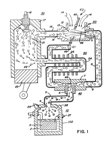
The exhaust gases 22 are fed via inlet pipe 31 to the cooling and spark arrestor chamber 50 and by pipe 24 into the mixing chamber 40. These gases from cooling and spark arrestor chamber 50 to mixing chamber 40 are controlled by a flow control valve 51 in pipe line 24.
How it is written
- (pipe 24) 1×
Drawings 1
-
To replenish the expended water the generator is connected via line 1 to a suitable water source. · Hydrogen Injection System
Where it is named · 1
Hydrogen Injection System 1×
-
pipe (pipe 24)
The exhaust gases 22 are fed via inlet pipe 31 to the cooling and spark arrestor chamber 50 and by pipe 24 into the mixing chamber 40. These gases from cooling and spark arrestor chamber 50 to mixing chamber 40 are controlled by a flow control valve 51 in pipe line 24.