Figure (8)
Figure (8)
How it is written
- (8) 2×
Drawings 1
-
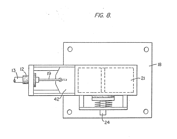
Figure 8 is a top view of the air intake valve to fuel mixing chamber. · Hydrogen Gas Injection for Internal Combustion Engine
On this figure 1
Where it is named · 2
Hydrogen Gas Injection for Internal Combustion Engine 2×
-
Figure 8 is a top view of the air intake valve to fuel mixing chamber.
-
Gas flow valve is described in detail with reference to Figure 3. The air intake 14 may be in a carburetor arrangement with an intake adjustment that adjusts the 10 plate 5? and also more fully described with reference to Figure 8.