Figure (3)
Figure (3)
How it is written
- (3) 3×
Drawings 1
-
The flow of the hydrogen gas is, of course, critical, therefore, there is incorporated in line 5 a gas flow valve 53 (Figure 1) to adjust the hydrogen flow. · Hydrogen Gas Injection for Internal Combustion Engine
On this figure 5
Where it is named · 3
Hydrogen Gas Injection for Internal Combustion Engine 3×
-
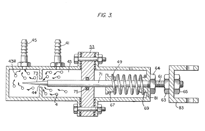
Figure 3 is the fine linear fuel flow control shown in Figure l.
-
Reference is made to Figure 3 illustrating precisely in a side view cross-section the fine linear fuel flow control 53. The hydrogen gas 4 enters chamber 45 via gas inlet 41. The hydrogen gas passes from chamber 43 via port or opening 44. The amount of gas passing from chamber 43 to chamber 43A is controlled by controlling the port opening 44.
-
Gas flow valve is described in detail with reference to Figure 3. The air intake 14 may be in a carburetor arrangement with an intake adjustment that adjusts the 10 plate 5? and also more fully described with reference to Figure 8.