(140)
Compressor
Also written vacuum pump
Where it is first named
… Also 125 is installed on Compressor 140 high pressure out-put. …
How it is written
- (compressor 140) 5×
- (vacuum pump 140) 2×
- (Compressor 140) 1×
Drawings 1
-
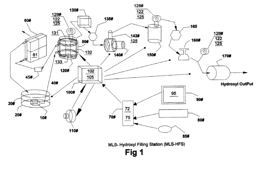
[0004] Drawing FIG. 1 shows the configuration of appa- ratus used in the MLS-hydroxyl filling Station (MLS-HFS). · Hydroxyl Filling Station
Where it is named · 8
Hydroxyl Filling Station 8×
-
Compressor (Compressor 140)
… Also 125 is installed on Compressor 140 high pressure out-put. …
-
vacuum pump (vacuum pump 140)
[0034] During the initial installation and after any repairs the total system is purge via the vacuum pump 140 by manual rerouting valuing to ensure that all-ambient air has been removed from the system.
-
compressor (compressor 140)
… 'he main functions of the testing is to ensure that the temperature electronics 131 attached to the hydroxyl cells 120 transfer- ring compressor 140 and analog pressure sensors 122 mounted on cells 120 high pressure tank 150 and discharge side of regulator 160 used for control and monitoring are working properly. …
-
vacuum pump (vacuum pump 140)
[0036] During the initial startup phase of the MLS-HFS system FIG. 1 the computer program 75 will configure the system for the purge sequence. This sequence will allow the vacuum pump 140 to draw down the hydroxyl cells 120 liquid trap 130 coupled to flow restriction value 135 and compressor 140 to removing all ambient air from them. …
-
compressor (compressor 140)
… This sequence will allow the vacuum pump 140 to draw down the hydroxyl cells 120 liquid trap 130 coupled to flow restriction value 135 and compressor 140 to removing all ambient air from them. …
-
compressor (compressor 140)
… When the cell pressures reaches a typical level of 5 pounds, the power source 110 is turned off and the compressor 140 is turned on starting the conveying of hydroxyl gases to high-pressure tank 150. …
-
compressor (compressor 140)
… When the hydroxyl cells 120 is drawn down to near zero pressure, the compressor 140 is turned off and power source 110 is turned back on starting the production cycle again.
-
compressor (compressor 140)
[0048] After the cell 120 has reached its upper pressure cutoff limit (typically 5LBS). The power source 110 is turned off enabling the compressor 140 to start its draw down and transferring of the gases to the high-pressure tank 150. …