(75)
Software Program
Also written computer program · program · computer control program
Where it is first named
(43) Pub. Date: Nov. 3, 2005 (54) MLS-HYDROXYL FILLING STATION (MLS-HFS) (75)
How it is written
- (software program 75) 5×
- (computer program 75) 3×
- (program 75) 2×
- (75) 1×
- (computer control program 75) 1×
Drawings 3
-
ABSTRACT · Hydroxyl Filling Station
-
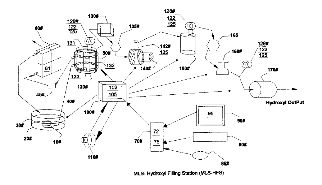
[0004] Drawing FIG. 1 shows the configuration of appa- ratus used in the MLS-hydroxyl filling Station (MLS-HFS). · Hydroxyl Filling Station
-
[0005] Drawing FIG. 2 shows the software display the operator uses to monitor and control the production of hydroxyl gascs and heat. · Hydroxyl Filling Station
Where it is named · 12
Hydroxyl Filling Station 12×
-
software program (software program 75)
[0012] 'The automatic control section in FIG. 1 consist of a computer 70 software program 75 video monitor 90 and its graphic operator display 95 (FIG. 2) pointer 85 keyboard 80 interface card 72 and I/O controller 100 with its driver electronics cards 102 and 105.
-
computer control program (computer control program 75)
[0027] The MLS-HFS FIG. 1 is a hydroxyl gas and heat generating system using a renewable source of liquid supply 30 such as water. It uses a computer control program 75 with display interface 95 for the monitoring, adjusting and con- trolling of the electronic and hardware apparatus and process logic. …
-
software program (software program 75)
[0032] The software program 75 FIG.1 has five main functions.
-
computer program (computer program 75)
[0036] During the initial startup phase of the MLS-HFS system FIG. 1 the computer program 75 will configure the system for the purge sequence. …
-
program (program 75)
… Once the program 75 has detected no leaks, it then readies the system for gas production by routing the gas flow from 120 to high-pressure tank 150 and then to output flash back protector 170.
-
program (program 75)
[0037] The program 75 starts off its production sequence by first turning on the cooling system consisting of liquid pump 10 that is submerse in liquid bath 30 contain in vessel 20. The cooling liquid 30 is pumped through cooling jacket 50 attached to the outside of cells 120 through Filter 45 and then through cooling air radiator 60. Fans attached to the radiator 60 are turned on for cooling.
-
computer program (computer program 75)
… The computer program 75 and its graphic display 95 is used by the operator to adjust the rate of gas production and set the upper limit that the low pressure cell 120 will charge to.
-
computer program (computer program 75)
[0049] During cell 120 operations, the temperature is monitored for out of limit conditions set by control 231 using the graphic display 95. Should the temperature reach an excess limit, the gas production is stopped and the computer program 75 alerts the operator of the problem. The cooling system 30 using water jacket 50 attached to ccll 120 helps reduccs the temperature 131 and allows for higher gas production.
-
software program (software program 75)
[0051] A listing related to software program 75 is depicted in text files attached to ePAVE and their file names are as follows: CombustAlIP1 through CombustAlIP19, Tank- TrackingDataFormP1-P2, TempTrackingFormP1-P2 and CellChargeTimeP1-P2.
-
software program (software program 75)
6. The system according to claim 1 further enhances the production of hydroxyls based on the software program 75 ability to control the production of hydroxyl gases; control- ling its process limits, controlling its storage and controlling its delivery via operator controller FIG. 2.
-
software program (software program 75)
7. The software program 75 according to claim 6 further enhances the safety af the production of hydroxyls based on the monitoring of high and low limits and either alerting the operator of the condition/s and/or stopping the production on device failures via operator controller FIG. 2.