(30)
Liquid Bath
Also written bath · liquid supply · liquid · system
Where it is first named
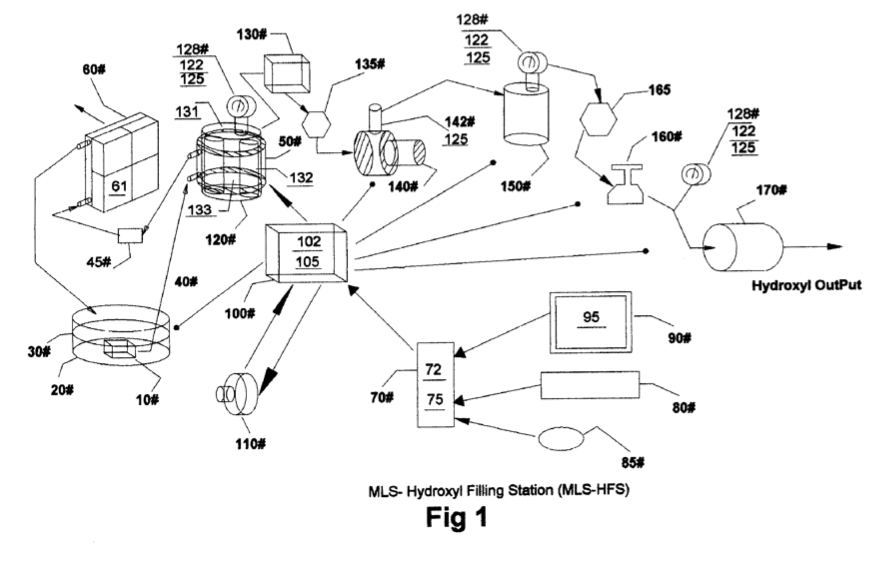
[0011] The heat removing section in FIG. 1 consist of a liquid bath 30 and its container 20, a liquid circulating pump 10, conveying conduits 40, cooling chamber 50 attached to hydroxyl generating cell 120, filler 45, radiator 60 and cooling fans 61 attached to it.
How it is written
- (liquid bath 30) 2×
- (bath 30) 1×
- (liquid 30) 1×
- (liquid supply 30) 1×
- (system 30) 1×
Drawings 1
-
[0004] Drawing FIG. 1 shows the configuration of appa- ratus used in the MLS-hydroxyl filling Station (MLS-HFS). · Hydroxyl Filling Station
Where it is named · 6
Hydroxyl Filling Station 6×
-
liquid bath (liquid bath 30)
[0011] The heat removing section in FIG. 1 consist of a liquid bath 30 and its container 20, a liquid circulating pump 10, conveying conduits 40, cooling chamber 50 attached to hydroxyl generating cell 120, filler 45, radiator 60 and cooling fans 61 attached to it.
-
liquid supply (liquid supply 30)
[0027] The MLS-HFS FIG. 1 is a hydroxyl gas and heat generating system using a renewable source of liquid supply 30 such as water. …
-
liquid bath (liquid bath 30)
[0037] The program 75 starts off its production sequence by first turning on the cooling system consisting of liquid pump 10 that is submerse in liquid bath 30 contain in vessel 20. The cooling liquid 30 is pumped through cooling jacket 50 attached to the outside of cells 120 through Filter 45 and then through cooling air radiator 60. Fans attached to the radiator 60 are turned on for cooling.
-
liquid (liquid 30)
[0037] The program 75 starts off its production sequence by first turning on the cooling system consisting of liquid pump 10 that is submerse in liquid bath 30 contain in vessel 20. The cooling liquid 30 is pumped through cooling jacket 50 attached to the outside of cells 120 through Filter 45 and then through cooling air radiator 60. Fans attached to the radiator 60 are turned on for cooling.
-
system (system 30)
[0049] During cell 120 operations, the temperature is monitored for out of limit conditions set by control 231 using the graphic display 95. Should the temperature reach an excess limit, the gas production is stopped and the computer program 75 alerts the operator of the problem. The cooling system 30 using water jacket 50 attached to ccll 120 helps reduccs the temperature 131 and allows for higher gas production.
-
bath (bath 30)
[0050] After extended running times, the water in cell 120 is replenished by bath 30 and filtered by 45 to help control the operating impedance of the cell.