Figure (1)
Figure (1)
How it is written
- (1) 8×
Drawings 1
-
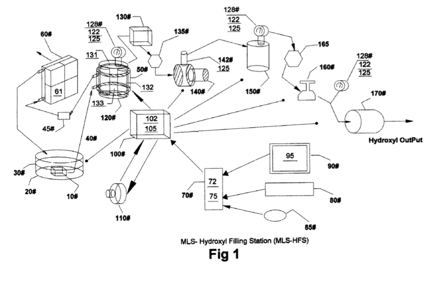
[0004] Drawing FIG. 1 shows the configuration of appa- ratus used in the MLS-hydroxyl filling Station (MLS-HFS). · Hydroxyl Filling Station
On this figure 13
- 30 Liquid Bath
- 50 Water Jacket
- 60 Radiator
- 61 Fans
- 75 Software Program
- 95 Graphic Display
- 110 Power Source
- 120 Cell
- 130 Liquid Trap
- 135 Flow Restriction Value
- 140 Compressor
- HFS MLS-HYDROXYL FILLING STATION
- MLS MLS-HYDROXYL FILLING STATION
Where it is named · 8
Hydroxyl Filling Station 8×
-
[0004] Drawing FIG. 1 shows the configuration of appa- ratus used in the MLS-hydroxyl filling Station (MLS-HFS).
-
[0010] FIG. 1
-
[0011] The heat removing section in FIG. 1 consist of a liquid bath 30 and its container 20, a liquid circulating pump 10, conveying conduits 40, cooling chamber 50 attached to hydroxyl generating cell 120, filler 45, radiator 60 and cooling fans 61 attached to it.
-
[0012] 'The automatic control section in FIG. 1 consist of a computer 70 software program 75 video monitor 90 and its graphic operator display 95 (FIG. 2) pointer 85 keyboard 80 interface card 72 and I/O controller 100 with its driver electronics cards 102 and 105.
-
[0027] The MLS-HFS FIG. 1 is a hydroxyl gas and heat generating system using a renewable source of liquid supply 30 such as water. …
-
[0031] The MLS-HFS FIG. 1 is monitored and controlled by the soft-ware program 75-computer 70 monitors 90 keyboard 80 pointer 85 and display interface 95, FIG. 2.
-
[0036] During the initial startup phase of the MLS-HFS system FIG. 1 the computer program 75 will configure the system for the purge sequence. …
-
[0047] Once the hydroxyl-generating cell 120 has been purged of Ambient air and production routing completed (FIG. 1). …