Figure (4)
Figure (4)
How it is written
- (4) 8×
Drawings 1
-
[0021] FIG. 5 · Hydroxyl Filling Station
On this figure 4
Where it is named · 8
Hydroxyl Filling Station 8×
-
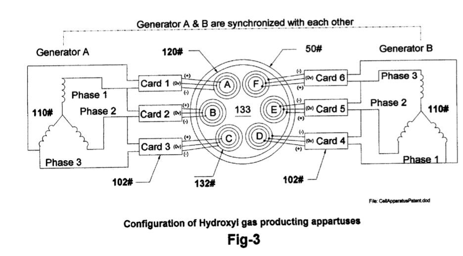
[0007] Drawing FIG. 4 shows the electronic impedance matching circuits 102 connected between the dual three phase generators (A&B) 110FIG. 3 and each of the wave- guide arrays 132 in cell 120FIG. 3. Note that only generator Ais depicted in the drawing VIG. 4 as being connected to arrays A-B-C using PC cards 1-3. Generator B is connected to arrays D-E-F using cards 4-6.
-
[0009] Drawing FIG. 6 shows the high frequency ringing signal located between test points T1 and T2 in impedance matching circuit 102 drawing FIG. 4. It is this ringing that also enhances the production of the hydroxyl gases in cell 120K 1G, 3.
-
[0019] FIG. 4
-
[0020] FIG. 4 shows the electrical circuits 102 used to drive the gas converting arrays 132F1G. …
-
[0020] FIG. 4 shows the electrical circuits 102 used to drive the gas converting arrays 132F1G. 3 submersed in a bath of water 133 in cell 120. The drawing FIG. 4 depicts three identical circuits connected to each of the three phase signals from % of the dual three phase generator A 110 FIG 3. …
-
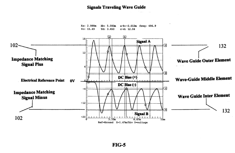
Note the de bias voltage +,- on either side of the center electrical reference point OV in FIG. 5. It is this bias voltage being modulated by multi polarity differential signals from 102 FIG. 4 that contributes to the wave-guide action of arrays 132. Also, the frequency of FIG. 5 is adjusted to match the electrical wave-length of the arrays 132 FIG. 3 and the impedance of water bath 133.
-
[0024] FIG. 6 shows the high-frequency ringing signals that contribute to the operation of the hydroxyl production. Just as a tuning fork rings when struck by a hammer, so does the wave-guide elements in arrays 132 immersed into the hydroxyl generating liquid 133 then struck by the electrical signals FIG. 5,6 from impedance matching circuits 102 depicted in FIG. 4.
-
3. The system according to claim 1 further enhances the production of hydroxyls based on the configuration of the impedance matching circuits FIG. 4.