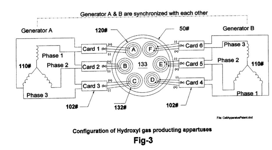
Figure (3)
Figure (3)
How it is written
- (3) 9×
Drawings 1
-
[0006] Drawing FIG. 3 shows the methods, configuration, and apparatus used in the hydroxyl producing cell 120 system. · Hydroxyl Filling Station
On this figure 5
Where it is named · 9
Hydroxyl Filling Station 9×
-
[0006] Drawing FIG. 3 shows the methods, configuration, and apparatus used in the hydroxyl producing cell 120 system.
-
[0018] FIG. 3 shows the configuration of our proprietary hydroxyl producing apparatus 120 consisting of dual three phase power source 110 impedance matching electronic circuits 102 and gas converters devices 132 submersed in a bath of water 133 in cell 120. …
-
… 4 depicts three identical circuits connected to each of the three phase signals from % of the dual three phase generator A 110 FIG 3. …
-
[0022] FIG. 5 Shows the composite signals applied to each of arrays 132 FIG. 3 submerges in water bath 133 in cell 120 and indicates the differential voltages used in the hydroxyl producing process MLS-HFS.
-
Note the de bias voltage +,- on either side of the center electrical reference point OV in FIG. 5. It is this bias voltage being modulated by multi polarity differential signals from 102 FIG. 4 that contributes to the wave-guide action of arrays 132. Also, the frequency of FIG. 5 is adjusted to match the electrical wave-length of the arrays 132 FIG. 3 and the impedance of water bath 133.
-
[0039] The result of this is just like the operation of a radio transmitter matching its signal to the air via the antenna impedance. Refer to FIG. 3 showing the relationship of this configuration to arrays 132, water bath 133 and Signals FIG. 5,6.
-
[0044] The impedance matching circuits 102FIG. 4 converts the sinewave signals from the three phase power source L1O FIG. 3 into multi polarity differential signals FIG. 5 that are applied to the triple wave-guide clusters arrays 132 A,B,C,D,L,I installed in cell 120.
-
2. The system according to claim 1 further enhances the production of Hydroxyls based on the configuration of the Hydroxyl gas producing apparatuses FIG. 3.
-
4. The system according to claim 1 further enhances the production of hydroxyls based on the application of the electrical signals FIG. 5 applied to signal traveling wave- guides 132 submersed in a bath of water 133 installed in cell 120 and configured as depicted in FIG. 3.