(102)
Circuits
Also written electronic circuits · electrical circuits · circuit · driver electronics cards · circuitry
Where it is first named
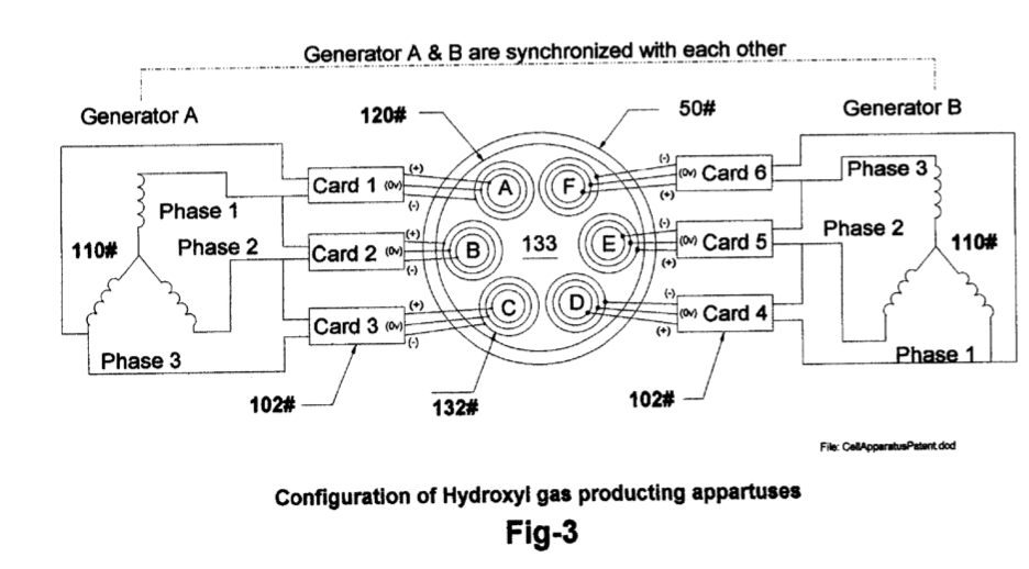
[0007] Drawing FIG. 4 shows the electronic impedance matching circuits 102 connected between the dual three phase generators (A&B) 110FIG. 3 and each of the wave- guide arrays 132 in cell 120FIG. 3. Note that only generator Ais depicted in the drawing VIG. 4 as being connected to arrays A-B-C using PC cards 1-3. Generator B is connected to arrays D-E-F using cards 4-6.
How it is written
- (circuits 102) 4×
- (electronic circuits 102) 2×
- (Circuit 102) 1×
- (circuitry 102) 1×
- (circuit 102) 1×
- (driver electronics cards 102) 1×
- (electrical circuits 102) 1×
Drawings 7
-
ABSTRACT · Hydroxyl Filling Station
-
[0004] Drawing FIG. 1 shows the configuration of appa- ratus used in the MLS-hydroxyl filling Station (MLS-HFS). · Hydroxyl Filling Station
-
[0006] Drawing FIG. 3 shows the methods, configuration, and apparatus used in the hydroxyl producing cell 120 system. · Hydroxyl Filling Station
-
Carries this number · Hydroxyl Filling Station
-
Carries this number · Hydroxyl Filling Station
-
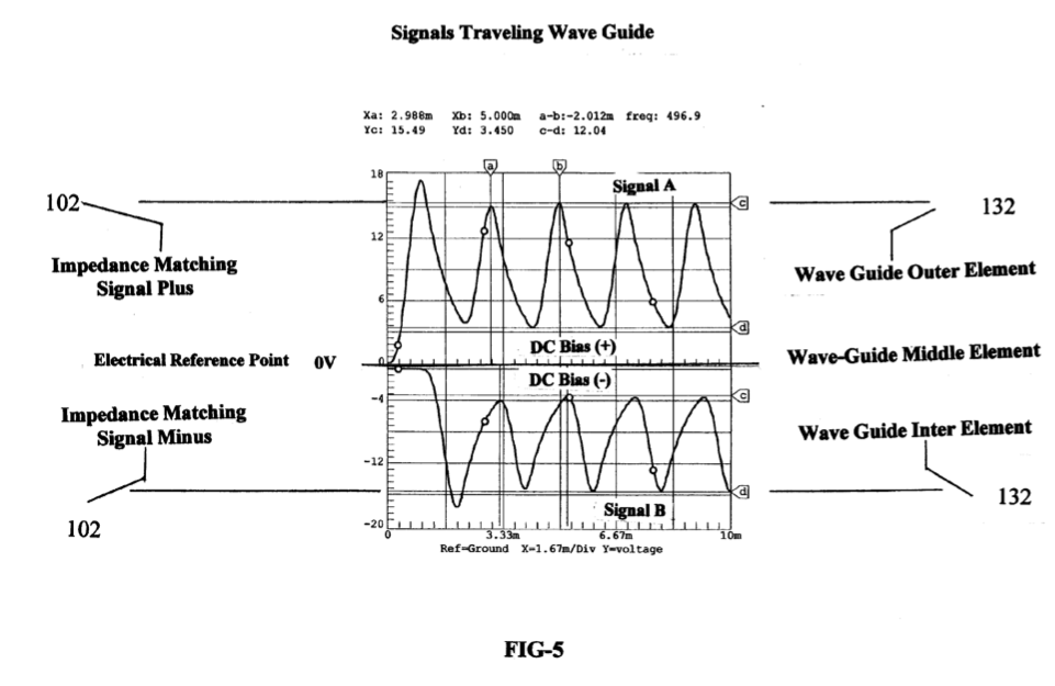
[0021] FIG. 5 · Hydroxyl Filling Station
-
[0005] Drawing FIG. 2 shows the software display the operator uses to monitor and control the production of hydroxyl gascs and heat. · Hydroxyl Filling Station
Where it is named · 11
Hydroxyl Filling Station 11×
-
circuits (circuits 102)
[0007] Drawing FIG. 4 shows the electronic impedance matching circuits 102 connected between the dual three phase generators (A&B) 110FIG. 3 and each of the wave- guide arrays 132 in cell 120FIG. 3. Note that only generator Ais depicted in the drawing VIG. 4 as being connected to arrays A-B-C using PC cards 1-3. Generator B is connected to arrays D-E-F using cards 4-6.
-
driver electronics cards (driver electronics cards 102)
[0012] 'The automatic control section in FIG. 1 consist of a computer 70 software program 75 video monitor 90 and its graphic operator display 95 (FIG. 2) pointer 85 keyboard 80 interface card 72 and I/O controller 100 with its driver electronics cards 102 and 105.
-
circuits (circuits 102)
[0013] Dual three phase power sources 110 and impedance matching circuits 102 provide the power needed to drive the hydroxyl cell 120.
-
electronic circuits (electronic circuits 102)
[0018] FIG. 3 shows the configuration of our proprietary hydroxyl producing apparatus 120 consisting of dual three phase power source 110 impedance matching electronic circuits 102 and gas converters devices 132 submersed in a bath of water 133 in cell 120. …
-
electrical circuits (electrical circuits 102)
[0020] FIG. 4 shows the electrical circuits 102 used to drive the gas converting arrays 132F1G. …
-
circuits (circuits 102)
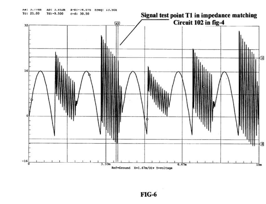
[0024] FIG. 6 shows the high-frequency ringing signals that contribute to the operation of the hydroxyl production. Just as a tuning fork rings when struck by a hammer, so does the wave-guide elements in arrays 132 immersed into the hydroxyl generating liquid 133 then struck by the electrical signals FIG. 5,6 from impedance matching circuits 102 depicted in FIG. 4.
-
electronic circuits (electronic circuits 102)
… The electronic circuits 102 mounted in driver 100 controls the production of the gases and heating while circuit 105 control the process and routing of the hydroxyl gas.
-
circuits (circuits 102)
… The power to the cell driving circuits 102 installed in driver 100 is supplied from a dual three phase isolated power source 110. …
-
circuitry (circuitry 102)
… The dual three-phase power source 110 is activated supplying frequency, amplitude, and phase signals to impedance matching circuitry 102. …