(10)
Catalytic Dome Assembly
Also written Dome Assembly · catalytic block assembly · hemispherical dome · Catalytic Dome
Where it is first named
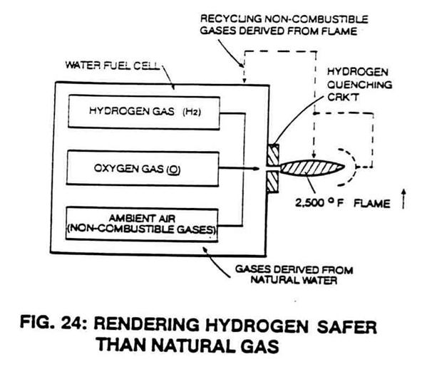
Catalytic Dome Assembly (10/30) positioned on top of and in space relationship to a Quenching Nozzle (20) affixed on top of and to a natural Water Fuel Cell, as illustrated in Figure 24 as to Figures 24SA, Figure 24SB, and 24SC.
How it is written
- (10) 2×
- (10/30) 2× with (30) Catalytic Dome Assembly
- (10/20) 1× with (20) Quenching Nozzle
Drawings 5
-
Water condensing unit (40) of Figure (39) is placed over said Dome Assembly (10/30). · Catalytic Block Assembly
-
This gas modulation process is further used to transport hydrogen gas through conventional gas lines, as shown in Figure 31. · Catalytic Block Assembly
-
In actuality, the hemispherical dome (10) of Figure 24SA performs as a secondary combustion zone. · Catalytic Block Assembly
-
Flame projection is achievable beyond six inches while flame temperature is variable up to and beyond 5,000 degrees F. · Catalytic Block Assembly
-
The figure it sits on · Catalytic Block Assembly
Where it is named · 5
Catalytic Block Assembly 5×
-
Catalytic Dome (10)
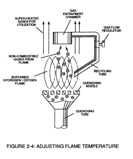
To ensure total and complete gas combustion during Fuel Cell operations, a Catalytic Dome (10) is placed on top of and in space relationship to said quenching nozzle (20), as so illustrated in Figure 24SA.
-
hemispherical dome (10)
In actuality, the hemispherical dome (10) of Figure 24SA performs as a secondary combustion zone.