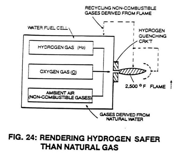
Figure (24)
Rendering Hydrogen Safer Than Natural Gas
How it is written
- (24) 8×
Drawings 1
-
Flame projection is achievable beyond six inches while flame temperature is variable up to and beyond 5,000 degrees F. · Catalytic Block Assembly
On this figure 8
- 1 Capture
- 2 Recycle
- 3 Non-Combustible Gases
- 6 Gases
- 9 Hydrogen/Oxygen Flame
- 10 Catalytic Dome Assembly
- 20 Quenching Nozzle
- 30 Catalytic Dome Assembly
Where it is named · 8
Catalytic Block Assembly 8×
-
The gas mixing ratio remains the same regardless of the gas rate of said Fuel Cell, as so described in Figure 24.
-
The ambient air gases (composed of non-combustible gases that do not support the burning process) act as a gas-burning modulator that retards the speed at which the hydrogen atoms unite with the oxygen atom during the gas burning process, see Figure 24 again.
-
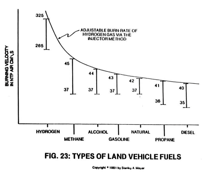
The gas mixing ratio of said Fuel Cell automatically adjusts the burn rate of hydrogen gas from 325 cm/sec to 42 cm/sec, co-equating the burn-rate of natural gas, as illustrated in Figure 24 as to Figure Graph 23.
-
To reduce the burn-rate of the hydrogen gas still further to lower flame temperature, simply capture (1) and recycle (2) the non-combustible gases (3) being expelled from said sustained hydrogen flame (9), as illustrated in Figure 24 as to Figure 24SC.
-
The Quenching Nozzle (20) of Figure 24SB as to Figure 24SC, Figure 24SA, and Figure 24, prevents spark-back into the Fuel Cell during gas ignition.
-
By simply igniting the Fuel Cell gases (6) expelling from said Quenching Nozzle (20) of Figure 24SB as to Figure 24, a hydrogen/oxygen flame (9) of Figure 24SB as to Figure 24 is sustained and maintained regardless of the gas-rate of said Fuel Cell.
-
By simply igniting the Fuel Cell gases (6) expelling from said Quenching Nozzle (20) of Figure 24SB as to Figure 24, a hydrogen/oxygen flame (9) of Figure 24SB as to Figure 24 is sustained and maintained regardless of the gas-rate of said Fuel Cell.