
ELECTRICAL POLARIZATION GENERATOR
PURPOSE: To produce electrical energy from natural water without consuming the water molecule atoms.
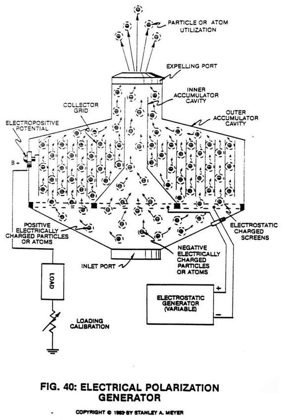
Circuit State: Moving electrically charged atoms (1/2) through an electrical grid system (50) inserted into a dual gas accumulator cavity (30/40) separated by an ambient air filtering screen assembly (20A) of opposite voltage polarity… forming Electrical Polarization Generator (90), as illustrated in Figure 40 as to Figure 8 subtitled “Regenerative Energy Feedback Module.”
ELECTRICAL CHARGED GASES
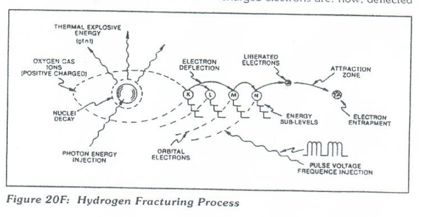
As shown in Figure 20F as to line graph 20FA and pulse train 20FB section A, the liberated gas atoms (Figure 24) (hydrogen, oxygen, ambient air gases) derived from natural water undergo the Electrical Polarization Process (Figure 2/3) become ionized when the opposite voltage zones (placed on opposite sides of said gas atoms) reach a certain voltage intensity… causing the negative electrically charged nucleus of said gas atom to be attracted to said positive electrical voltage zone… while, at the same time, the positive charged nuclei of the same gas atom is attracted to said negative electrical voltage zone, satisfying the opposite polarity attraction law of physics.
|
|
|
Increasing voltage intensity (Voltage potential by way of amp restriction) removes additional electrons from said gas atoms… at a given electron light frequency injection (nuclei light absorption).
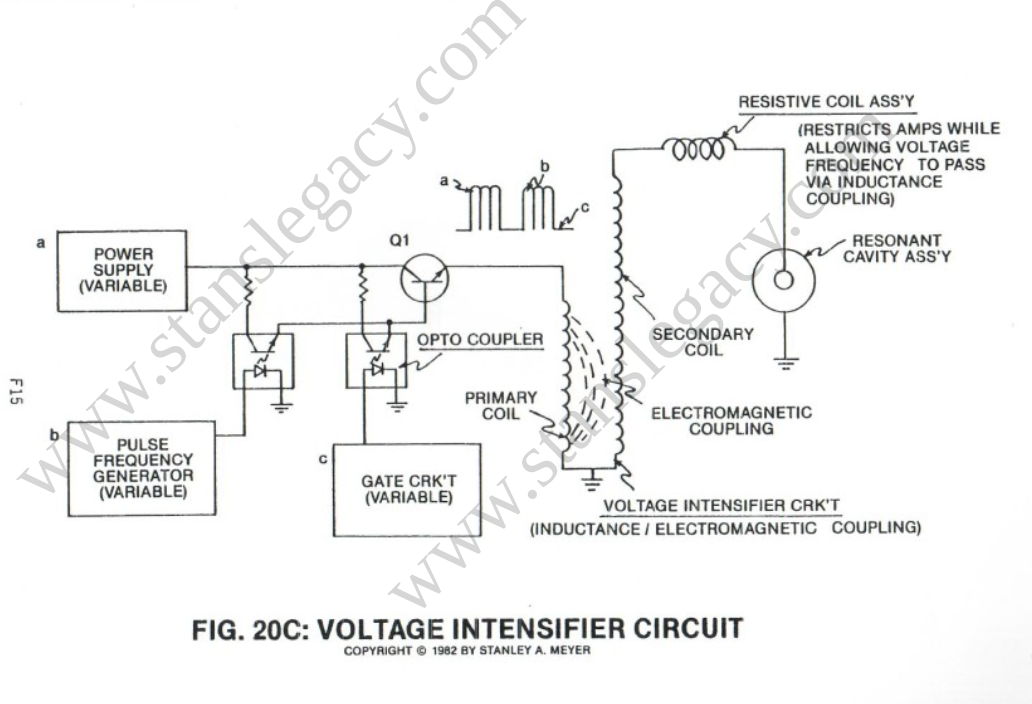
This said Atomic Polarization Process further aids the electron deflection process by deflecting said electrons to a higher energy state, see Figure 20F as to Figure 20C.
Voltage Intensifier Circuit (VXA) prevents electron replacement.
The water molecule is exposed to the same voltage stimulation process.
ELECTRON ENTRAPMENT
In cases where electron ejection does not occur, the laser absorbed atoms may accept the liberated and/or free-floating electrons… causing electron entrapment, see Figure 20F again.
ION GAS FORMATION
The atoms having missing electrons now become positive charge gas ions (1) while atoms having more electrons than normal become negative charge gas ions (2).
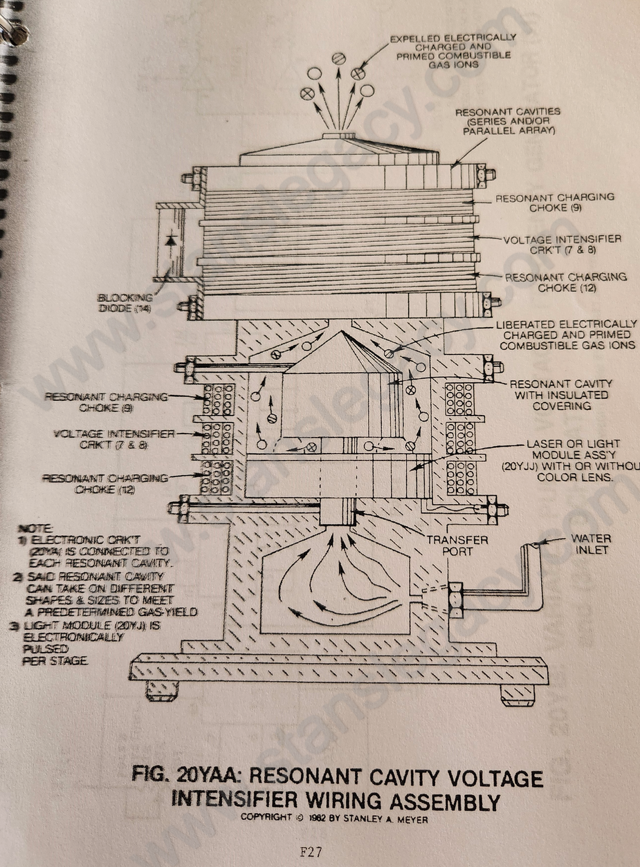
After ionic gas formation, the electrically charged gases are expelled out of said Fuel Cell (Figure 20YAA) as to Figure 3B and enter into said Electrical Polarization Generator (90) of figure 40.
 |
|
ELECTRONIC GAS FILTERING TECHNIQUE
As the electrically charged gases (1/2) pass into, through and beyond inlet gas accumulator cavity (10), the negative charged screen-grid (4) attracts the positive charged gas ions while the positive charged screen-grid (5) attracts the negative gas ions.
The Electrostatic Generator (6) (Voltage Intensifier Circuit 9XA) applied said opposite voltage potential to said screen-grids during the Gas Filtering Process.
The attracted and moving positive charge gas ions (1) now pass through and beyond screen-port (4) into accumulator cavity (30);
while, at the same time, the attracted and moving negative gas ions (2) pass through and beyond screen-port (5) into a second accumulator cavity (40)... performing the gas filtering process.
Accumulator cavities (30/40) are electrically isolated from one another to prevent electrical discharging of said gas ions during application use.
ELECTROPOSITIVE POTENTIAL
Since the positive electrically charged gas ions (1a xxx 1n) are exposed to said Collector Grid (50) constructed of electrical conducting plates material (6a xxx 6n) such as stainless steel T304, the Collector Grid Assembly (50) becomes positive electrically charged due to the Electrical Skin Effect between said charged gas ions and said electrical conduction plate (6).
Electrical Skin Effect occurs when the electrical field that surrounds the gas ions touches the electrical conduction plate (6), as illustrated in Figure 40.
The resultant positive electrical potential (7) is now applied to positive electrical terminal (8).
To increase said positive electrical potential (7) (voltage potential) across said electrical terminal (8), simply increase the surface areas of said electrical plates (6a xxx 6n) while increasing the number of electrically charged particles (1a xxx 1n) touching said expanded collection plates.
PERFORMING ELECTRICAL WORK
Since electrical differential exists between electrical ground (11) and said positive electrical terminal (8), electrical work (consuming electron flow) is now performed when an electrical load is placed between said electrical points (8/11).
Said Electrical Work occurs when the negative electrically charge electrons from ground connection (11) move toward and through said electrical load (9) to positive electrical terminal (8).
The traveling electrons continue along an electrical pathway (electrical conductor attached between said terminal post (8) and said plates) to electrical conduction plates (6a xxx 6n)...
exposing the moving electrons to the moving gas ions (1a xxx 1n) of opposite electrical polarity...
allowing the moving negative electrically charged electrons to be accepted by the positive charged gas atom (1) having missing electrons...
satisfying the law of atom stability of physics.
To maintain a constant flow of electrons toward said electrical terminal (8), simply maintain the gas-flow through the gas accumulator cavity (30).
To increase amp flow (speed up electron movement), increase said gas flow rate.
Of course, amp flow is minimized between said electrical load (9) and said electrical terminal (8) since said electrical load consumes electrical power (consuming electrons) in the form of electrical heat.
GAS ION DISPOSAL
The negative charged gas ions (2a xxx 2n) passing through gas accumulator (40) is simply discharged through gas exit port (12) while gas ions (1a xxx 1n) passing through gas accumulator cavity (30) are discharged through a separate exit port (13).
The expelling gases are simply recombined for hydrogen gas utilization beyond said exit port (12/13).