Hydrogen Gas Gun Technology
G16
Objective: To utilize or trigger the atomic energy-yield of water on demand.
Voltage interaction with the water Molecule: to applied Voltage Graph Figure 20FB
NATURAL STATE
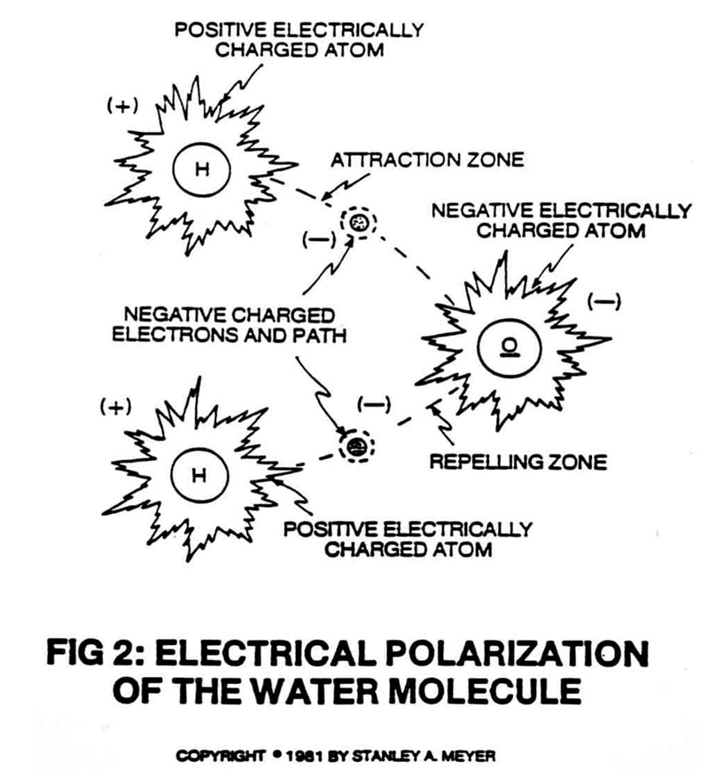
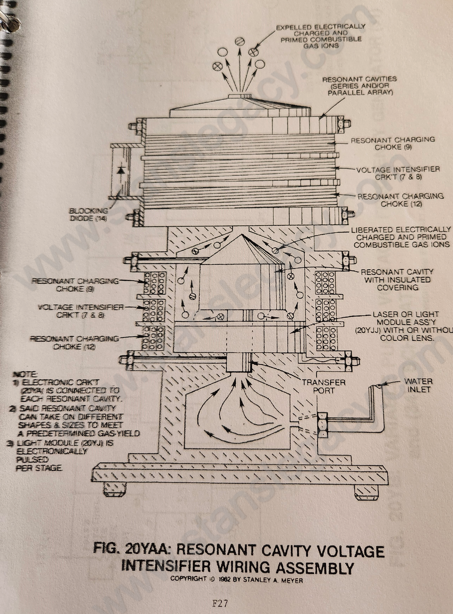
Prior to Voltage stimulation, the water molecules are randomly (A) dispersed throughout the water medium inside said Resonant Cavity Fuel Cell, as shown in Figure 20YAA as to Figure 2 and Figure 3.
|
|
|
ANALOG VOLTAGE FORMATION
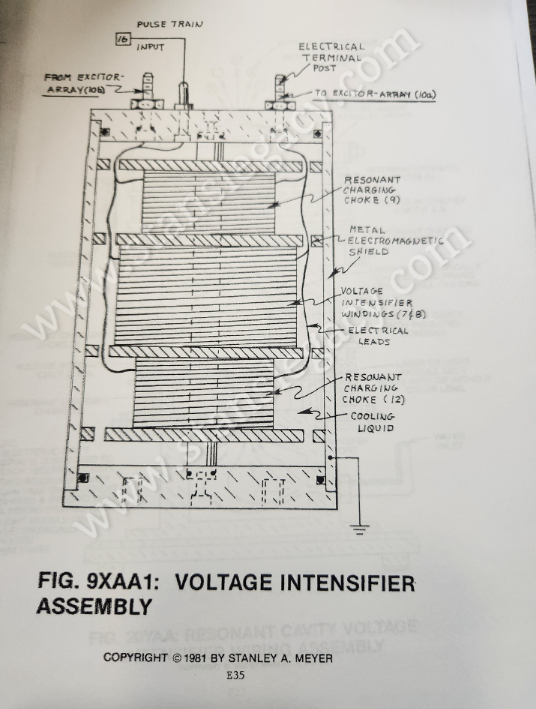
As unipolar Voltage Pulse Train (53a xxx 53n) of Figure 20FB Section AA is applied to said voltage intensifier assembly 9XA1 as to Figure schematic 9XA, an analog voltage pulse train (55) of Figure 20FB is formed in a linear direction.
 |
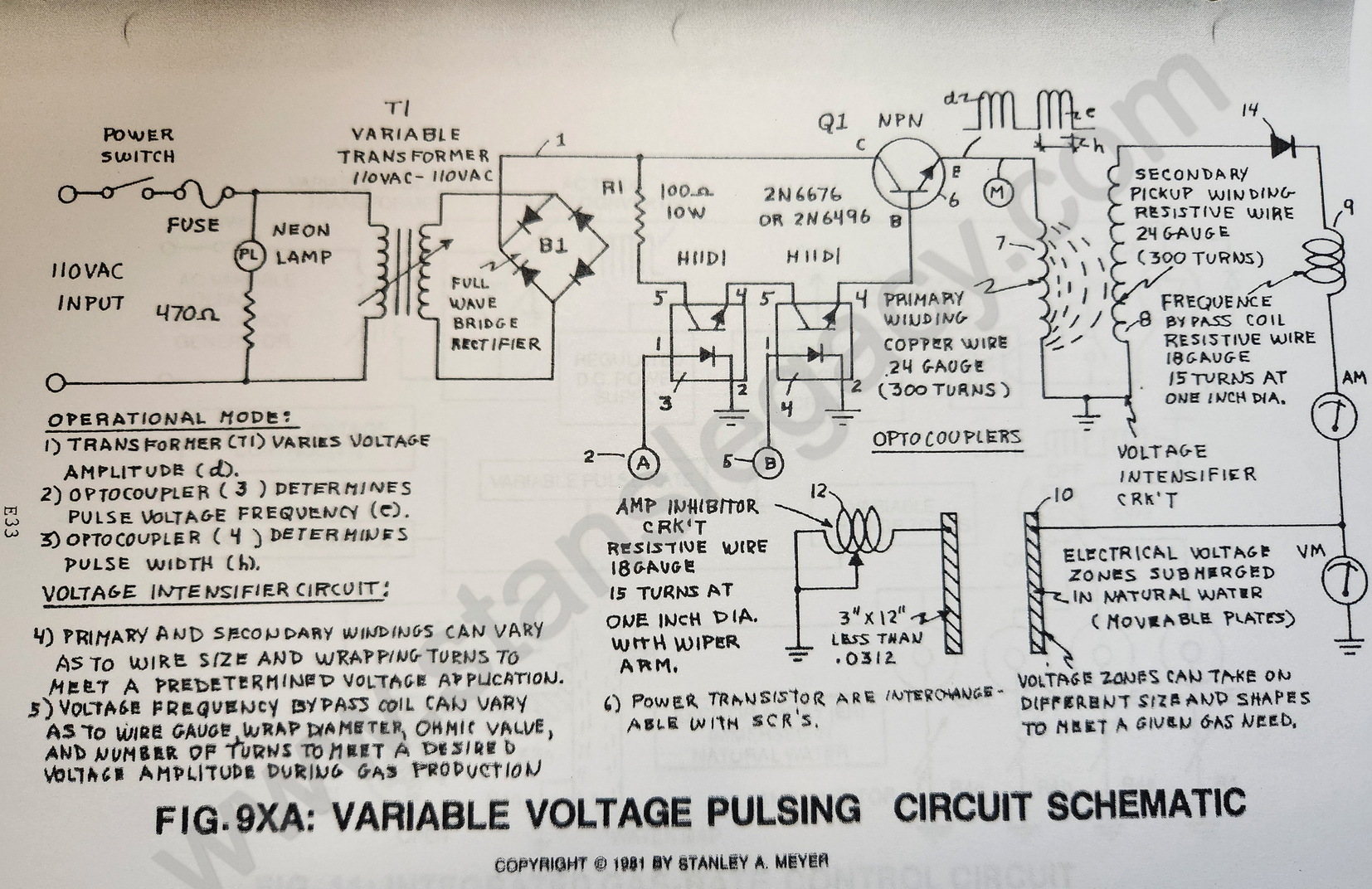 |
The Step Charging Effect (across said excitor-plates) causes the pulsing voltage potential to increase from a low energy state (A) to a high energy state (J) during each pulsing-train, as illustrated in Figure 20FB.
Typically, the analog voltage range (voltage intensity) is from zero to 5,000 volts and above.
The increasing voltage potential is always positive in direct relationship to negative ground potential during each pulsing-stage.
Voltage polarity on said excitor-plates (voltage fields) remains the same during each pulsing-operations.
Said positive and negative voltage fields (voltage zones) are formed simultaneously.
Water Molecule Alignment
Since the water molecule naturally exhibits opposite electrical fields (the two hydrogen atoms being positive electrically charged relative to the negative electrically charged oxygen atom), the analog voltage pulse (B) of Figure 20FB causes said random water molecules to spin and orientate themselves in reference to said voltage fields.
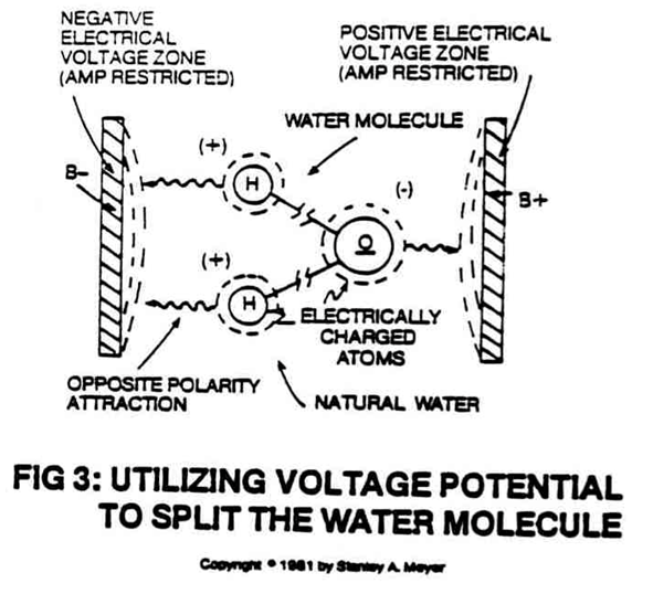
The positive electrically charged hydrogen atoms of said water molecule being attracted to said negative voltage plate; while, at the same time, the negative electrically charged oxygen atom of the same water molecule is attracted to the positive voltage plate.
Said opposite voltage fields are formed on opposite sides of said water molecules.
 |
|
Several gigavolts (billionth of a volt) of applied power is all that is needed to initiate said molecular orientation. Amp restricting circuit 9XA as to 20YD allows said orientation process to occur.
G17
Polarization Charge
Analog Voltage Level (C) now causes the orientated water molecules to align themselves end to end between said voltage zones (excitor plates) in a linear direction since the positive voltage field intensity is also increasing in a linear function.
The Analog Voltage Level (C) is now entering into the microvolt range (millionth of a volt).
Once molecular alignment occurs, molecular movement stops, as illustrated in Figure 3.
Since the positive charged hydrogen atoms of said inline molecules are in opposite direction to the negative charged oxygen atoms, a polar charge now exists between said voltage zones.
|
|
 |
Molecular Elongation
As the Analog Voltage Level (D) approaches the Millivolt range (thousandth of a volt), the stationary water molecules start to become elongated since said electrically charged atoms are being attracted toward opposite electrically charged voltage zones...disrupting mass equilibrium of said water molecule, as illustrated in Figure 3.
Atom Liberation
 Analog Voltage Level (E) simply disrupts said electrical equilibrium of said water molecule undergoing said atom displacement.
As the water molecule is exposed to said voltage level (E) the electrical charge of said atoms becomes greater in intensity...
causing the covalent bonding (sharing electrons) between said atoms to be terminated or switch-off, as shown in Figure 2.
The moving negative charged electron is being attracted toward the positive charged hydrogen atom while, at the same time, the negative charged oxygen atom repels said moving electron. This electrical stimulating effect now establishes the Electrical Polarization Process.
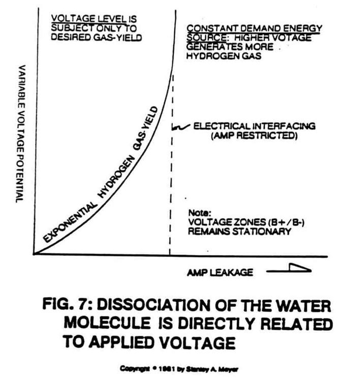
Dissociation of the water molecule is directly related to applied voltage.
Higher voltage means higher gas-yield, as shown in Figure 7.
The variable voltage fields can exceed hundreds of volts during fuel cell operations.
Liquid to Gas Ionization
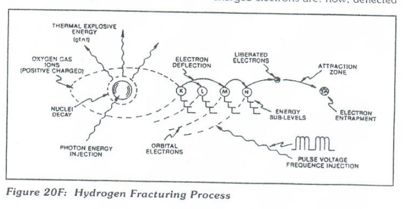
Once said voltage potential (F) reaches a certain threshold, the exposed water molecules and liberated hydrogen, oxygen, and ambient air gases start to ionize...losing or gaining electrons...causing atom destabilization...disrupting the electrical and mass equilibrium of said atoms, as illustrated in Figure 20K as to Figure 20F and Figure 20G.
| Figure 20K |
Figure 20F
|
Figure 20G
|
Said positive voltage field attracting said negative charged electrons; while, at the same time, the positive charged nuclei is attracted to the negative voltage field.
Atom stabilization does not occur since the voltage fields are repetitive without polarity change.
Several thousands of volts trigger said ionization state.
G18
Electrical Charging Effect
As the ionized gases (being electrically charged) are allowed to accumulate inside said Fuel Cell, the electrical charging effect (G) can be greater than said applied voltage...speeding up the Electrical Polarization Process still further.
Particle Impact
Particle Impact (H) occurs when the liberated ionized gases (Positive and Negative electrically charged gas atoms) are voltage deflected through the Electrical Polarization Process.
Laser or Photon Injection
To help reach gas ionization while highly energizing said atom nuclei (see Figure 20F and 20K again), Laser or Photon energy (I) of a predetermined wave length and pulse-intensity (see Figure 20FB Section B8) is exposed to and absorbed by said gas ions.
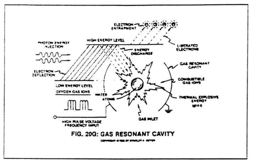 The highly energized nuclei causes electron deflection to a higher orbital state, as further illustrated in Figure 20F as to Figure 20G and 20K.
Laser-pulse (or light-pulse) as well as light intensity is varied to match the absorption rate of said gas nuclei.
Atomic Destabilization
Continued exposure of said gas ions (F) to said laser or light energy (I) during voltage stimulation (A through H) prevents atomic stabilization (J).
Atomic Triggering on Demand
Since the liberated atoms are highly energized combustible gas ions, gas thermal ignition occurs when said combustible gas ions enter into and pass through Optical Thermal Lens assembly of Figure 20FC.
The Electrically Charged and Laser primed combustible gas ions are expelled through and beyond a quenching circuit and reflected back and forth through a thermal heat zone prior to atomic breakdown beyond exiting ports.
The Deflection Shield superheats (beyond 3,000 degrees F) the combustible gas ions while said exiting-ports are small enough to allow gas pressure to form inside said thermal zone.
The atomic energy-yield from water is simply controlled by varying the applied voltage pulse-train (53a xxx 53n) since said thermal-lens assembly is self-adjusting to the flow-rate of said ionized and primed gases.
G38/39
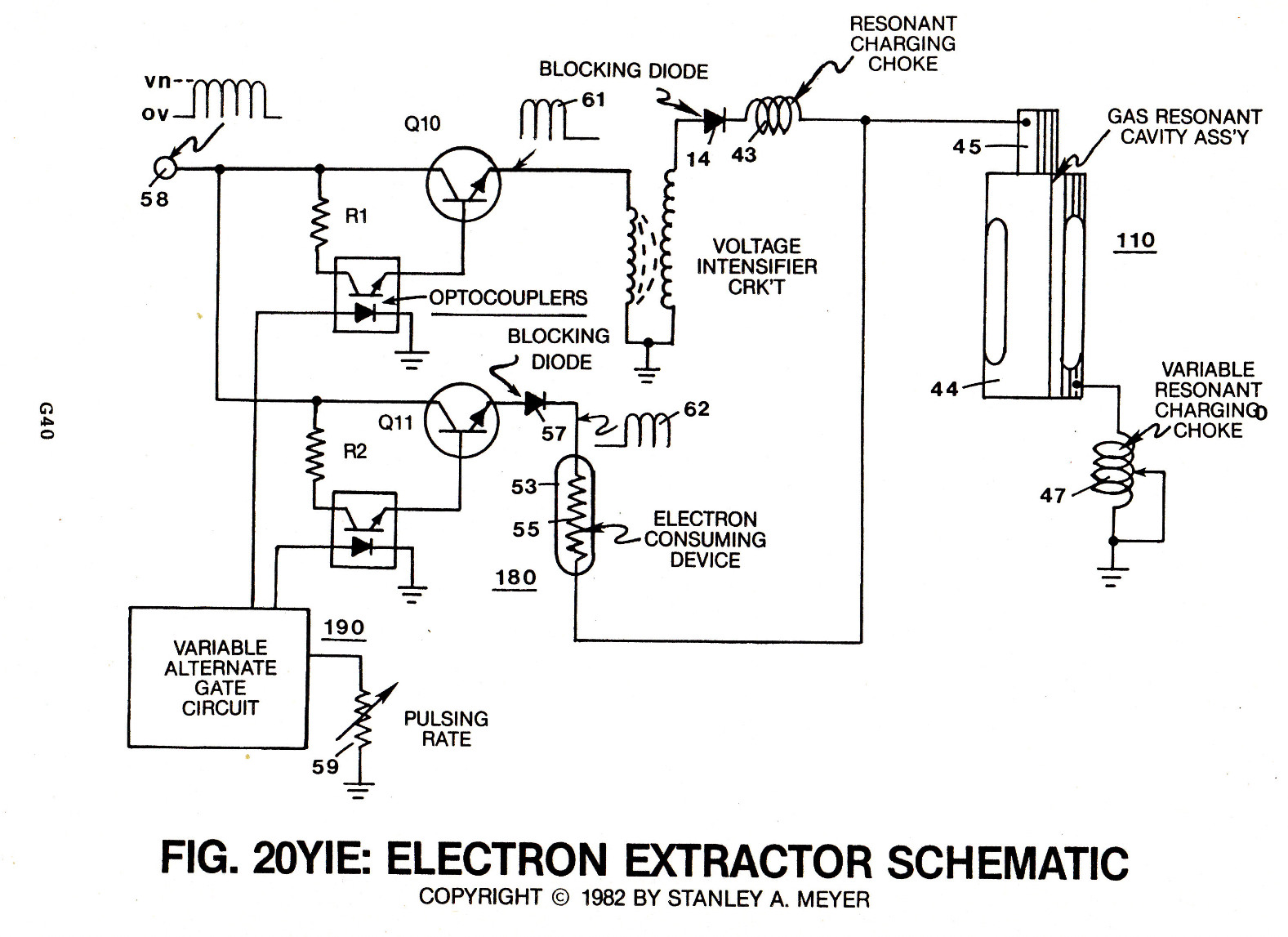
ELECTRON EXTRACTOR GRID AND RELATED CIRCUIT
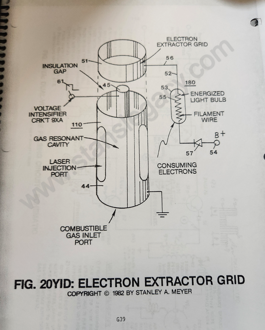
T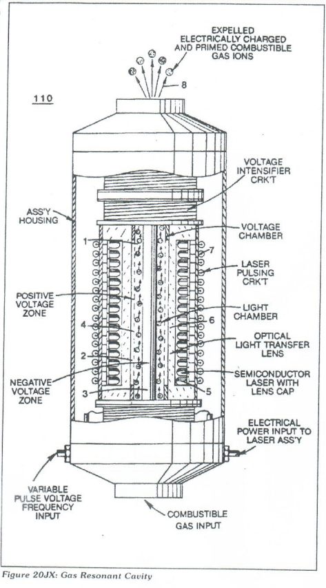 o further stimulate and help the ELECTRON ENTRAPMENT PROCESS beyond the atomic level (taking away and capturing the liberator electrons during the Hydrogen Fracturing Process) (see Figure 206 as to Figure 20F, once again), an ELECTRON EXTRACTOR GRID (51) is placed on top of and in space relationship to said Gas Resonant Cavity Structure (110), as illustrated in Figure 20YID as to Figure 20JX.
The Electron Extractor Grid (51) is attached to an electrical circuit (180) that allows electron flow (56) to pass to an electrical load (53) by electrical wire (52) when a positive electrical potential (54) is placed on opposite side of said electrical load (53)
...electrical load (53) being a typical light bulb or amp consuming device.
As the positive electrical potential (54) is switched on or pulse-applied, the negative charged electrons liberated from the Hydrogen Fracturing Process are drawn away from said Gas Resonant Cavity (110 of Figure 20 JX) and enters into said light bulb (53) (by way of opposite polarity attraction) having resistive filament wire (55).
As said moving electrons (56) interact with said resistive wire (55) am consumption (consuming amps) takes place by way of heat dissipation in the form of light energy.
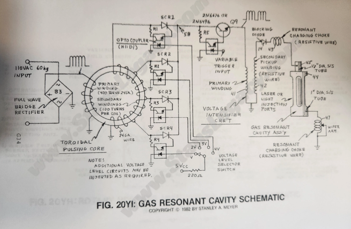
To help prevent electron oscillation or deflection during the Hydrogen Fracturing Process, said amp consuming electrical circuit (180) can be directly connected to said Gas Resonant Cavity positive electrical voltage zone (45), as illustrated in schematic 20IE.
|
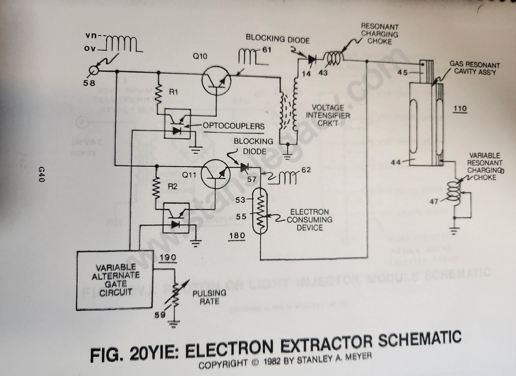 |
The electrical voltage zone (45) through blocking diode (14) is now synchronized with pulse train (62) via alternate gate circuit (190).
As pulse train (61) is gated "ON," pulse train (62) is switched "OFF."
Once pulse train (61) is terminated pulse train (62) is now reformed.
Repetitive formation of said alternating positive wave forms (61/62) now allows the Hydrogen Fracturing Process to take place in a sequential manner with the Electron Extraction Process.
Blocking diode (14) directs the electron flow (56) to said Electrical Load (53) while resistive wire (55) prevents voltage leakage during pulse train (61) "ON" time.
Blocking diode (57) prevents electron leakage to power switch circuit (Q11).
The Electron Extraction Process is simply maintained during gas flow-rate change by varying trigger pulse (59) in direct relationship to applied voltage level (58).
The Electron Extraction Process also prevents spark-ignition of said combustible gases traveling through said Gas Resonant Cavity (110) since electron build-up is being prevented.
 |
 |
|
|
|
|
|
G40