
DUAL VOLTAGE RESONANT "Q"
Electron Flow vs Voltage Amplitude vs Voltage Frequency:
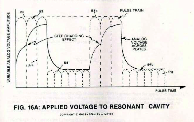
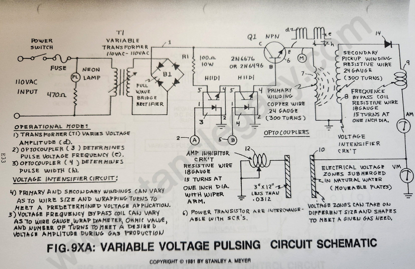
In reference to Voltage Intensifier Circuit 9XA as to dual-voltage schematic 20YA and pulse voltage waveform 16A/20YA Section AA, the following operational parameters exist:
Electronic Interfacing Circuit:
- Secondary Pickup Winding (resistive wire coil) (42)
- Blocking Diode (14)
- Resonant Charging Choke (resistive wire coil) (43)
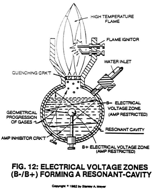
- Resonant Cavity Inner Surface (45) (forming a Positive Electrical Voltage Zone),
- Resonant Cavity Outer Surface (44) (forming a Negative Voltage Zone)
- Voltage zones surface area (44/45) form the Capacitance value of said Resonant Cavity Assembly (4) of Figure 12. Natural Water inside said Resonant Cavity Assembly (44/45) provides the dielectric value between said voltage zones (44/45), resonant charging choke (47) to electrical ground forms and completes the Voltage Intensifier Circuit 9XA as to 20YA.
|
|
 |
Circuit Operational Parameters:
Purpose:
To form opposite Electrical Voltage Zones while restricting amp flow during the Electrical Polarization Process (splitting the water molecule by way of voltage stimulation).
Secondary Pickup Winding (42)
The resistive wire-coil (42) allows a voltage potential (electromagnetic induction process) to form across said pickup-coil (42), while the resistive value (Ohm value) of said coil-wire acts as a resistor which opposes electron flow from said circuit electrical ground (48).
Scientific Fact: Since electrons are negatively electrically charged, electron flow (amp flow) always moves toward positive electrical potential... if allowed.
Block Diode (14)
Since Blocking Diode (14) conducts electricity in one direction "ONLY" (direction of schematic arrow), electron flow or movement toward said pickup coil (42) is prevented during said Positive Voltage Potential formation.