
Steam Resonator
Steam Resonant Cavity
Purpose: To produce superheated steam by way of pulsating voltage fields on opposite sides of a water molecule while restricting amp flow.
 Circuit Stage:
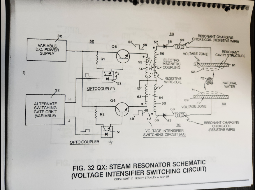
Integrating alternate pulsing circuit (Q5) as to (Q6) to said voltage intensifier switching circuit (AA) arranged in a dual polarity configuration, as illustrated in Figure 32QX titled Steam Resonator Schematic.
SEQUENTIAL GATE CIRCUIT
As shown in Figure 32QX, variable gate circuit (32) is a two-state switch device which is directly linked to both optocoupler (51) and optocoupler (52).
As (H) nears ground or low state (zero volts), optocoupler (52) is triggered "on," allowing power switch (Q5) to form unipolar voltage pulse (53).
Once said gate circuit (32) changes voltage state (low to high or vice versa), trigger pulse (J) turns on optocoupler (51) that "switches" on power switch (Q6) to form another unipolar voltage pulse (48).
Triggered pulse (H) is now terminated, switching off said voltage pulse (53).
Repeating said alternate gate switching (H) as to (J) applies an alternate duty pulse of positive polarity to said Voltage Intensifier Switching Circuit (AA), as shown in Figure 32QX.
Gate circuit (32) varies or regulates said duty pulse (53/48) up to one megahertz or more.
Voltage Intensifier Switching Circuit
As duty pulse (53) is formed across primary coil (54), an electromagnetic field (55) is produced and coupled with pickup coil (56)...forming a voltage potential (57) across said pickup coil (56).
Since said pickup coil (56) is composed of resistive wire, amp flow is being restricted within the voltage intensifier circuit (60) as previously described in WFC Tech Brief Section 4 titled Voltage Attenuation Circuit Design Specs.
The produced voltage potential (57) now gates "ON" unidirectional diode (58)...allowing said voltage potential (57) to pass to, through, and beyond in-line charging Choke Coil (59) to Excitor Plate (61)...forming positive voltage field (62).
Amp flow is further reduced since said inline choke coil (59) is also composed of resistive wire.
Voltage field (62) ceases to exist when said duty pulse (53) is terminated or "switched-off."
Repeating said duty pulse (53) sets up a pulsating voltage field (62) of positive polarity across said Excitor Plate (61) while circuit (60) restricts amp flow to a minimum value.
Excitor Plate (61) is made of Stainless Steel T304 material to prevent chemical interaction or material oxidation with natural water.
Blocking diode (58) prevents electrical shorting from occurring across said pickup coil (56) during said pulsing operations.
Gated pulse (H) can be proportionally changed via gate circuit (32) to "concentrate" or "expand" said applied voltage (57) to said voltage zone (61) during pulsing operations.
As on-time (53) increases, off-time (49) proportionally decreases. Pulse adjustment is reversible.
Voltage Intensifier Circuit (70) is an exact duplicate of interfacing circuit (60) and performs in like manner...except duty pulse (48) is applied to a second Excitor Plate (69) exposed to the opposite side of the same water molecule.
Together Voltage Intensifier Circuits (60) and (70) form Voltage Intensifier Switching Circuit (AA) of Figure 32QX.
Excitor Plate (61) and Excitor Plate (69) form Steam Resonant Cavity (80) of Figure 32.
Steam Resonant Cavity (80) can take on different design configurations to meet a predetermined steam-yield.
Voltage Field Oscillation
Dual pulsing circuit (50) linked to said Voltage Intensifier Switching Circuit (AA) simply switches or alternates a unipolar positive voltage pulse from one Excitor Plate (61) to another Excitor Plate (69) in a sequential manner to produce superheated steam by way of voltage deflection of the water molecule.
To increase the rate of steam production, simply increase the formation-rate of said voltage fields (62/71) across said voltage zones (61/69).
 Electrical Charging of the Water Molecule
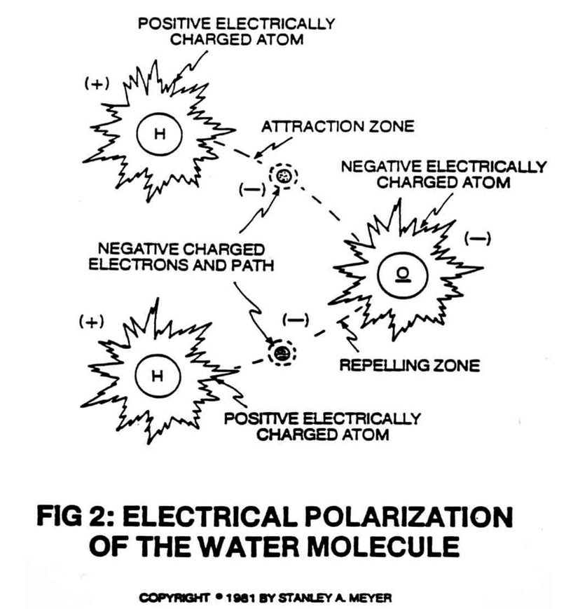
Since the water molecule is naturally held together by an electrical field of opposite polarity, the hydrogen atoms take on a positive electrical charge relative to the negative charge oxygen atom, as illustrated in Figure 2 of said WFC Tech Brief.
Said electrical fields of opposite polarity surround said water molecule atoms.
The sum total of the positive electrical charges equals the sum total of the negative electrical charge between said unlike atoms...
providing electrical equilibrium of the water molecule.
Voltage Deflection of the Water Molecule
By simply applying a positive voltage potential (62) across said Excitor Plate (61) for a moment of time, the water molecule (72) of Figure (2) as to Figure (32QX) is now deflected or moved toward said voltage zone (61) due to opposite electrical attraction force between said negative charged oxygen atom of said water molecule and said positive electrical voltage zone (62).
Switching "OFF" said electrical voltage field (62) while switching "ON" said positive electrical voltage field (71) now causes said water molecule (72) to "deflect or move" in opposite direction towards said voltage zone (69)...colliding with other water molecules undergoing the same voltage deflection process...generating heat due to particle impact, as illustrated in Figure 32.
|
|
|
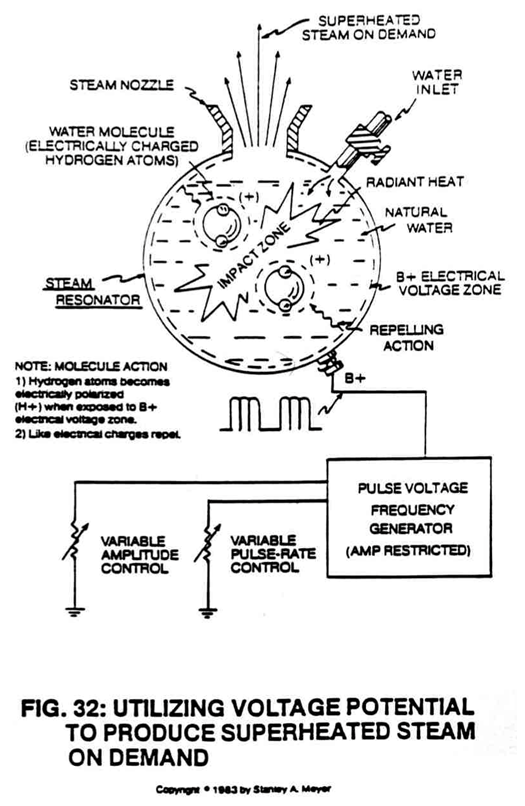
Repetitive formation of said voltage fields (62/71) on opposite sides of said water molecule oscillates the water molecules in a back-and-forth pattern between said voltage zones (62/71)...converting said natural water into superheated steam for utilization.
To increase steam-yield still further, simply increase the voltage amplitude of said D.C. power supply (30) of Figure 32QX.
Caution: DO NOT SIMULTANEOUSLY APPLY AN OPPOSITE ELECTRICAL VOLTAGE FIELD ACROSS SAID WATER MOLECULE UNLESS YOU WANT TO PRODUCE HYDROGEN GAS ON DEMAND. THIS PROCESS IS CALLED "THE ELECTRICAL POLARIZATION PROCESS."