
Voltage Attenuation Circuit
Objective: Voltage Disassociation of the Water Molecule.
A) VARIABLE POWER SUPPLY:
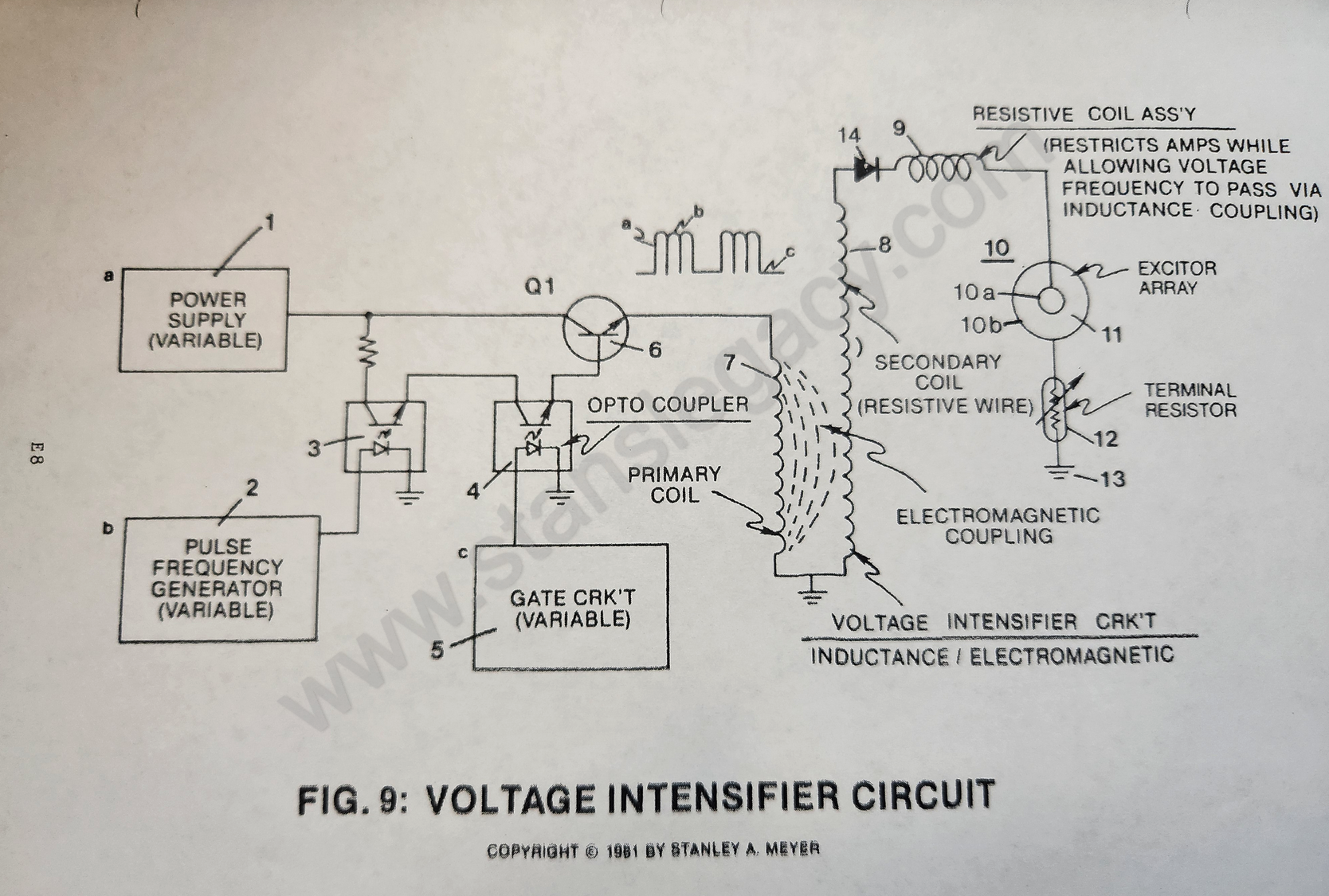
Purpose: (See (1) of Figure 9)
Any type of conventional A.C., to D.C. or D.C. power supply (non-regulated) where an adjustable voltage range from less than one volt to 110 volts and up (first-stage to voltage attenuation).
B) VARIABLE PULSE VOLTAGE FREQUENCY GENERATOR:
Purpose: Not to allow a constant voltage source to be applied to excitor array (voltage zones) while attenuating voltage amplitude for gas-rate control.
Circuit Stage: (1) (2) as to (3) of Figure 9
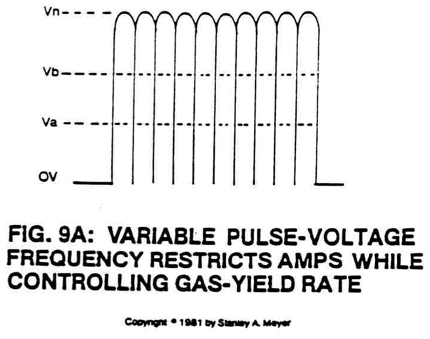
Optocoupler (3) is a photosolation switch that when triggered by pulse frequency generator circuit (2) causes power supply voltage (1) to be attenuated as per Figure 9A, setting up a pulse voltage frequency.
By varying the triggering rate of said pulse generator (2) from 1HZ to 1MHZ, said pulse voltage frequency (9A) is likewise varied.
Phototransistor of said optocoupler (3) now allows said pulse voltage frequency amplitude (Va-Vn of Figure 9A) to be varied from less than one volt to over 110 volts via said variable power supply (1).
Circuit Function:
The variable pulse voltage frequency (9A) is adjusted to keep amp flow restricted during first-stage to amp restriction by allowing said voltage amplitude (Va-Vn of Figure 9A).
The variable pulse voltage frequency amplitude (Va-Vn of Figure 9A) is directly related to hydrogen gas production on demand (second stage to voltage attenuation).
Both above said functions can be performed simultaneously or apart.
C) VARIABLE GATE CIRCUIT:
Purpose:
To switch off and on said generated pulse voltage frequency (9A) at a variable time rate while maintaining said voltage amplitude control (Va-Vn of Figure 9A).
Circuit Stage: (4) (5) as to (6) of Figure 9.
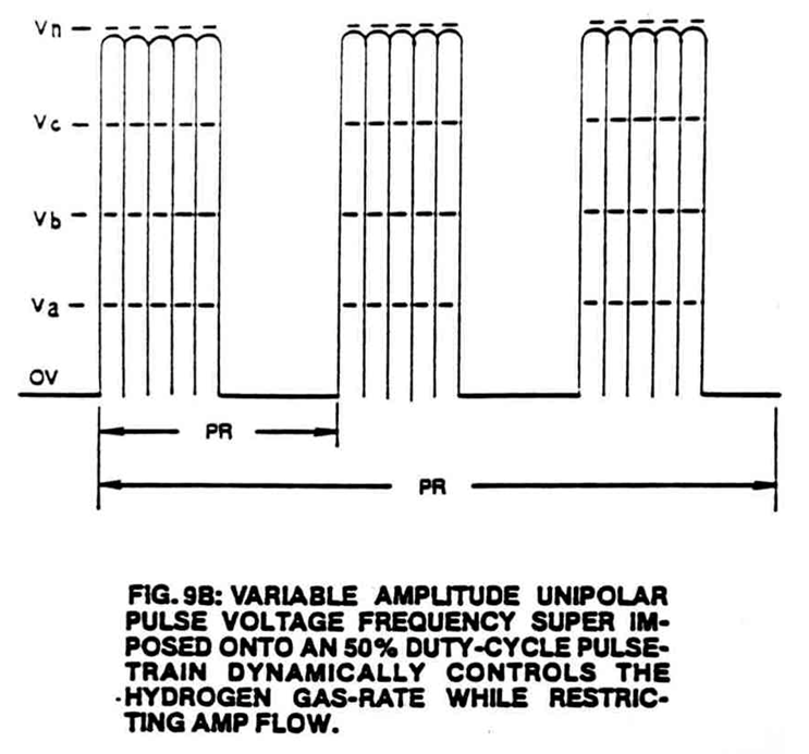
Optocoupler (4) is another photoisolation switch that when triggered by variable gate circuit (5) (a second variable triggering circuit) causes said pulse voltage frequency wave form (9A) to be altered as shown in Figure 9B.
The gated pulse train (16, on time) as to (17, off-time) is adjustable from 1% to 100% duty time.
|
|

As on-time (16) increases, off-time (17) proportionally decreases, allowing more voltage pulses to be applied to said excitor's array (Va-Vn of Figure 9A) (ER).
To reduce the number of voltage pulses, simply reverse the pulse-train frequency.
Once the gated pulse train (15) is set as to maximizing gas production, the duty-cycle pulse (15) is now varied from one duty-pulse per second alternation (15a) to one hundred duty-pulses per second duration (15n).
The voltage amplitude (Va-Vn of Figure 9A) remains variable as to gas needs.
Of course, optocoupler (4) gates on power transistor Q1 as herein described.
Circuit Function:
- The adjustable pulse-train simply "concentrates" or time-regulates the applied pulse voltage frequency (9A), allowing for higher voltage amplitude (third-stage to voltage attenuation).
- The variable gated-pulse (15) is now adjusted to reduce amp flow further while allowing voltage amplitude (Va-Vn) and pulse voltage frequency (9A) to be adjusted to "tune-in" for higher gas-yields (second stage to voltage attenuation).
D) VOLTAGE INTENSIFIER CIRCUIT:
Purpose: To step up power supply voltage (1) while maintaining said variable voltage amplitude (Va-Vn) control, said variable pulse frequency (9A) control, said variable gate (9B) control, and performing a third, fourth, and fifth step to amp restriction.
|
|
Circuit Stage: (6) (7) as to (8)
As power transistor Q1 is actuated to produce variable waveform (9B), the output wave form (9B) is now superimposed onto a primary coil wrap around a secondary coil of greater size (more turns of wire), forming a voltage intensifier transformer, see Figure 9.
The primary coil is composed of copper wire, whereas the secondary coil is composed of resistive wire. Both types of wire are coated with an insulated material to prevent electrical shorting.
Opposite to the input-to-output leads, the two said coiled wires are joined together to form an electrical ground.
Only transformer paper is used to wrap said coils.
By way of transformer-action (electromagnetic coupling), said waveform (9B) is now transferred to said secondary coil, performing voltage amplification while said pulse-train remains the same.
The step-up voltage amplitude is, however, directly related to power supply voltage (1) and attenuated during gas production.
The pulse-train is likewise attenuated as herein described.
To help prevent amp leakage from occurring during gas production, said resistive wire is used to retard amp flow through said secondary coil (8) voltage potential is developed across said pick-up coil (*) leads (third stage to amp restriction and fourth-stage to voltage attenuation.)
The air space between said primary and said secondary coils provides a step-gap to amp flow since no electrical "junction" or "connection" exists inside said air-gap (fourth-stage to amp restriction).
Circuit Function:
The amp restricting functions occurring prior to said transformer-action prevents "power drop" during pulsing operations under load (fifth-stage to amp restriction).
E) HIGH FREQUENCY VOLTAGE BYPASS COIL:
Purpose: To restrict amp flow while allowing voltage potential to pass through said bypass coil (9 of Figure 9) via electromagnetic induction coupling.
Circuit Stage: (8) as to (9)
As pulse voltage potential is developed across said secondary coil (8) leads, said developed voltage pulses are now allowed to pass through and beyond said bypass coil (9) by way of electromagnetic inductance.
Inductance coupling occurs when said voltage pulses generate an oscillating magnetic field around said bypass coil (9). The incoming voltage pulse creates a magnetic field that passes through said coil (9) windings.
Once the applied incoming voltage pulse is terminated, as herein described, the magnetic field now collapses, allowing said collapsing magnetic field to pass through said coil (9) once again during said voltage off-time.
Amp restriction occurs since said coil winding (9) is composed of resistive wire (sixth-stage to amp restriction).
Circuit Function:
a) To duplicate incoming voltage pulse train while performing amp restriction without heat build-up.
F) ELECTRICAL VOLTAGE ZONES:
Purpose:
To establish and set up voltage zones (10) of opposite polarity in natural water without inducing chemical oxidation.
 Circuit Stage: (9) as to (10)
The pulse voltage waveform (mirror imaged of Figure 9B) developed at said bypass coil (9) output lead is now transferred to stainless steel plates (excitor array) submerged in natural water.
Due to the skin-effect phenomenon, voltage forms across said plates of Figure 9, forming voltage zones of opposite polarity. Switching off said voltage pulse eliminates said voltage zones.
Reapplying said voltage pulse re-establishes said voltage zones once again.
Repetitive formation of said voltage pulses now establishes an oscillating voltage field between opposite polarity plates called voltage zones (ER).
In addition, said voltage zones take on the geometrical shape of said material.
Circuit Function:
a. The physical property of stainless steel T304 material is ideally suited since said material does "not" oxidize when exposed to liberated hydrogen and oxygen atoms in water having no voltage potential applied to said material.
As per above said "operating conditions," lab certification tests show the decomposition rate of said stainless steel material at .0001/yr.
b. Chemical interaction is also held to a minimum since amps are being restricted (as herein described) in natural water having no more than 20 parts per mission of any type of contaminates (seventh-stage to amp restriction)
Rule of thumb: Do not increase electrical conductivity of natural water by adding chemicals.
Gas production occurs in all natural water, even the purest form of distilled water, when voltage potential is applied to its dielectric constant.
Remember: Distilled water is an insulator to the flow of current (amps).
Point-of-Discovery:
If amps are being restricted during gas production, then voltage stimulation is dissociating the water molecule. This process is now called the "electrical polarization process," see Water Fuel Cell Technical Brief as to Exhibit AX (taken from McGraw-Hill Encyclopedia of Science and Technology Volume 14, page 405).
G) VOLTAGE CHAMBER:
Purpose: To eliminate voltage leakage to surround water during gas production.
Circuit Stage: (10) as to (20 of Figure 9D)**
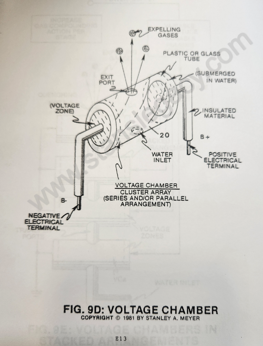 By simply surrounding said voltage zone with an electrical insulator (Teflon) such as plastic or glass (see 20 of Figure 9D), said applied voltage pulses retain a much higher voltage potential during gas production.
Simply, said insulator cavity (20) seals off said voltage gap by preventing electrical leakage to said water supply.
Voltage concentration is now accomplished during gas production.
Circuit Function:
a) To maintain a higher voltage potential on said voltage zones by preventing electrical leakage beyond said voltage gap (sixth-stage to voltage attenuation).
b) Said voltage chambers are relatively "small" or "tiny" in size and can be arranged in parallel or series array, as illustrated in Figure 9C, or stacked in series relationship (exit port to inlet port) for "compounding gas production" (inducing particle impact into said voltage process), as illustrated in Figure 9E.
c) To prevent electrical leakage from occurring outside said voltage chamber, simply use a plastic (insulator material) housing to form said fuel cell.
 |
 |
H) SEQUENTIAL GATE CONTROL:
Purpose: To increase gas production beyond voltage attenuation while keeping power loss to a minimum.
Circuit Stage: (6) as to (7) (8) (9) (10) as of Figure 9C.
To extend gas production beyond the limits of a single excitor array (10) (and voltage zones), simply add more excitor array (ER as to 10) to said gas producing process, as shown in Figure 9C.
Each excitor-array (10) is connected to the same circuit with said voltage intensifier circuits (7) (8) and (9), which, in turn, are sequentially pulsed (19) to minimize power loss during gas production.
Circuit Function:
- Said sequential gate control circuit (19) is variable to control gas production beyond said voltage attenuation controls (seventh-stage to voltage attenuation).
- By variable pulsing circuit (1) (2) (3) (4) (5) as to (6) remains under power, however additional excitor-array (10) as herein described is added, power loss or drainage is held to a minimum (ninth-stage to amp restriction).
I) TERMINAL RESISTOR:
Purpose: To provide ohmic balance between said bypass coil (9) and said ground terminal (13) to help eliminate electron deflection within said power circuit during gas production.
Circuit Stage: (9) as to (13)
Terminal resistor (12 of Figure 9) is affixed to said excitor-array (10) on ground side (see Figure 9 again) to prevent counter electron deflection or movement within said interfacing circuit (8 as to 9).
Said terminal resistor (12) is composed of resistive wire wrapped in a coil configuration, taking the shape of said bypass coil (9).
Said bypass coil (9) and said terminal resistor (12) are the same in likeness.
An adjustable terminal lead (wiper arm) is affixed, however, to said terminal resistor (12).
Circuit Function:
- Helps prevent distortion of said pulse voltage waveform (9B) during gas production.
- Helps prevent transformer "humming" during power loading.
- Said terminal resistor (12) can be adjustable to help "tune-in" gas production.
IA) VOLTAGE INTENSIFIER CIRCUIT: ELECTRONIC COMPONENT INTERACTION:
Purpose: To utilize Resonant Charging Chokes to aid amp restriction.
Circuit Stage: (7) (8), (14), (9), (10) as to (11), (10B), (12) and (13).
The electrical control circuit used to start and control the gas generation process is shown in the schematic diagram of Figure 9.
This diagram consists of the major components required to control this process and its described in the order of process flow (from left to right across the schematic).
ELECTRICAL DESCRIPTION OF COMPONENT:
 The following is a description of each of these electrical components, their interconnections, their functions and the processing signals generated to disassociate the water molecule by way of voltage stimulation.
The water fuel cell is also one of the major components of this circuit with its physical make-up, calibration, volume, and characteristics of water (dielectric constant, capacitance, and electrical charge).
SIGNAL FLOW:
- The voltage intensifier circuit (Figure 9) converts the variable DC supply voltage (1) into a continuous high-frequency positive unipolar signal (Figure 9B) to control the variable duty cycle pulse train (Figure 9B) to control the power supply (1).
- The high voltage pulse train (16 of Figure 9B) is then coupled to the stainless steel excitor plates (10A) submerged in water, producing gas output.
- By way of transformer-action (electromagnetic coupling), the step-charging effect of Figure 9B enhances the gas-yield by maintaining a stable voltage zone.
CONTINUOUS OPERATIONS:
The volume of gas from the fuel cell is now controlled by the variable duty cycle pulse train (one to one hundred percent). The variable DC power supply (1) serves as the optimum plate load of the excitors during resonant tuning.
CIRCUIT SETUP AND CALIBRATION
The setup and calibration of this circuit is one of the major factors in the operation of this system and must be completed before use.
The water fuel cell is filled with water (10 & 11), the excitor plates adjusted for the correct distance and volume, then connected to the voltage intensifier circuit (Figure 9).
The circuit is then tuned to match the resonant characteristic of the total system by adjusting the pulse frequency generator (2) and the series resonant charging choke-coil (12).
The amount of gas output from the water fuel cell is then adjusted by the variable gate control circuit (5) and the level of the variable DC power supply (1).
TRANSIENT STARTUP
During the transient startup period, the unidirectional diode (14) is in its non-conducting state and isolates the water fuel cell from the high voltage multiplying component (8).
This diode allows the fuel cell to take on a positive charge during each high positive voltage pulse.
Also the diode prevents the fuel cell from discharging during pulse train off times.
During the initial charging of the fuel cell, the modulator inductor coils (9 and 12) serve as a DC current limiter because of their resistive value (Resistive wire).
The low "Q" resonant charging circuit consisting of fuel cell (10 and 11) in series with choke-coil (9 and 12) has the capability of storing electrical energy during each of the successive DC pulse inputs.
The charge of the fuel cell is further enhanced by the choke-coils (9 and 12) during diode (14) disconnect times.
As a result, a step-charging effect (voltage), as illustrated in Figure 9BB, is applied across the fuel cell (10).
Also during pulsing operations, the impedance of the charging circuit increases, resulting in the reduction of current flow from the high voltage drive circuit (7 and 8).
 |
|
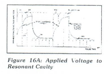
This step charging effect is also illustrated in Figure 16A.
CONTINUOUS OPERATIONS
The volume of gas from the fuel cell is now controlled by the variable duty cycle pulse train (one to one hundred percent). The variable DC power supply (1) serves as the optimum plate load of the excitors during resonant tuning.
J) ROTARY PULSE-VOLTAGE FREQUENCY GENERATOR:
Purpose: To interface said pulsing circuit (Figure 9) with another type of power supply.

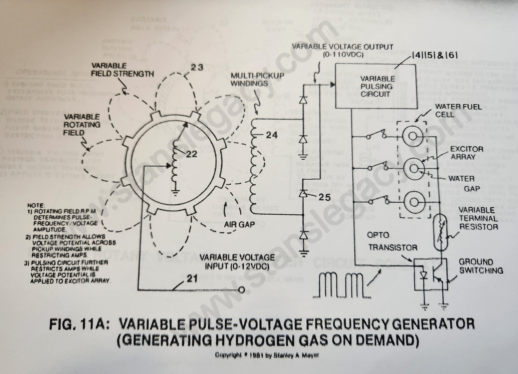
Circuit Stage: (21) (22) (23) (24) (25) as to (4) (5) and (6)
As shown in Figure 11A, the variable amplitude pulsing circuit (21) allows armature coils (22) to be electrically energized to produce pulsating electromagnetic fields (23) which are then rotated toward and through pickup coils (24), producing a variable A.C. pulse train.
Bounce network system (25) converts said variable A.C. pulses to variable D.C. pulses.
Variable gating circuit (4) (5) as to (6) simply switches off and on said D.C. pulse train, duplicating pulse voltage waveform (9B).
Circuit Function:
a) To adjust magnetic field strength (23) in such a way as to allow voltage potential only to be developed across said pickup coils (24) connected to said gating circuit (see Figure 9).
Due to electrical "isolation," amp draw is now restricted since said magnetic field strength remains weak. (tenth step to amp restriction)
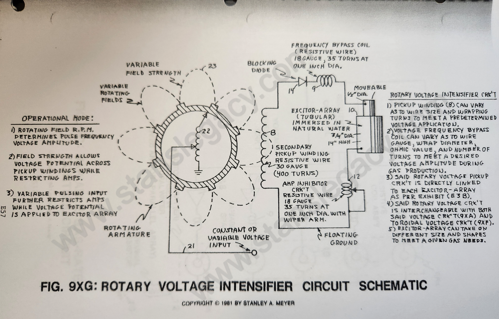
b) To change said generated voltage pulses, simply vary the rotational speed of said armature. (eighth step to voltage attenuation)
c) To vary voltage pulsing amplitude, simply vary the amplitude voltage of said electrical power input (21). (ninth step to voltage attenuation)
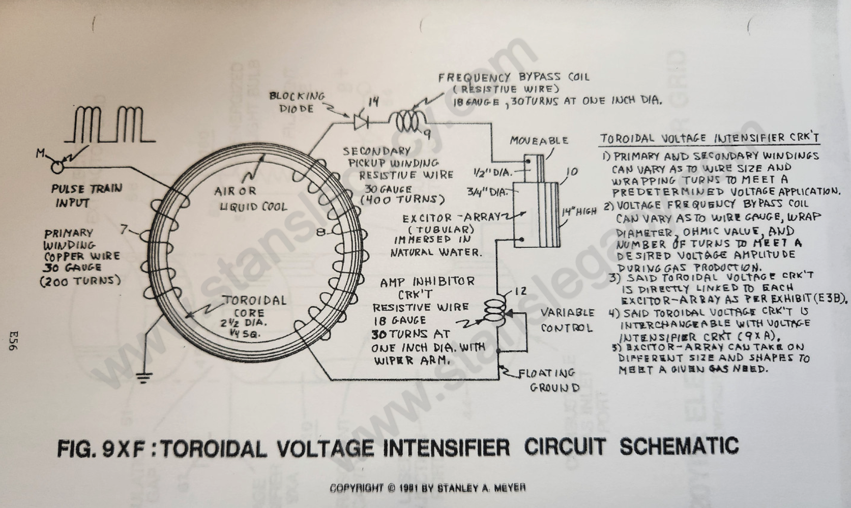
d) To restrict amps still further by using resistive wire to form said pickup winding, see Figure 9XF and Figure 9XG.
 |
 |
Operational Comments:
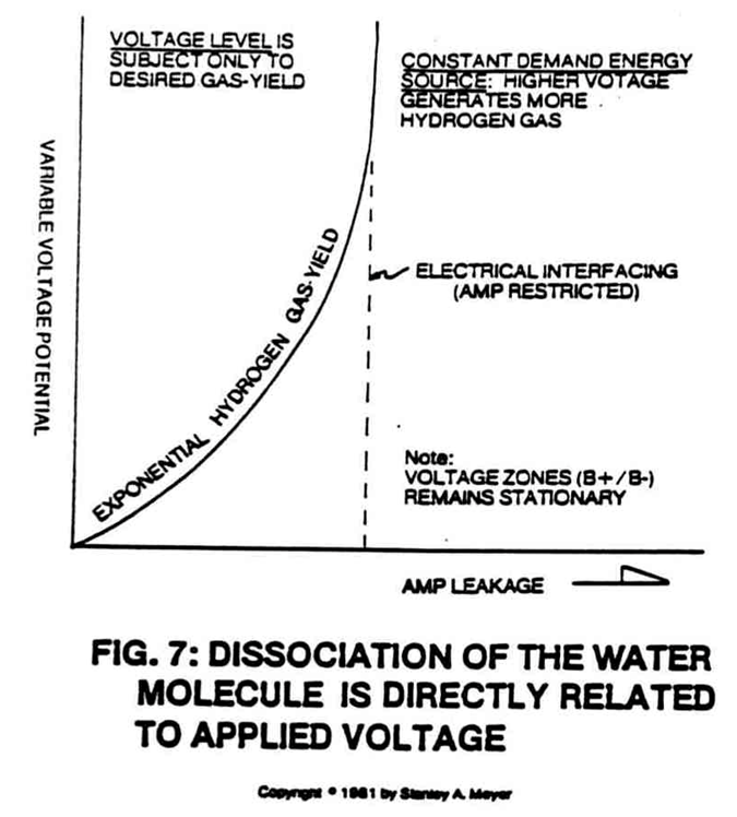
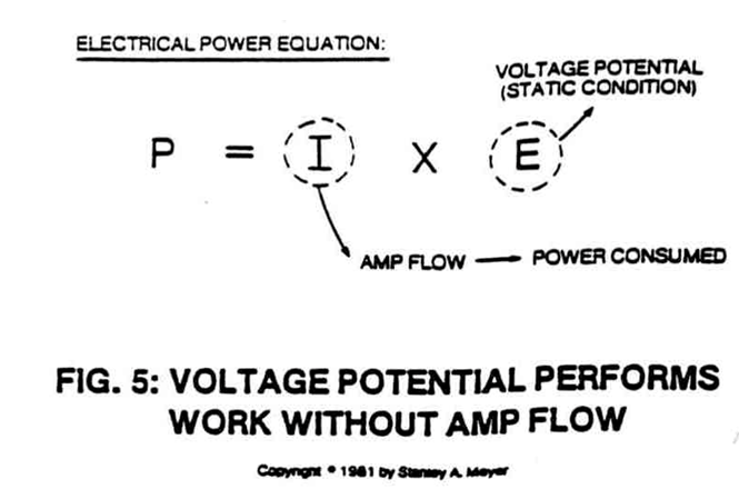
As herein described, the ten-stage amp restricting circuit now uses said nine-stage voltage attenuating feature to produce hydrogen gas on demand as per Figure 7 in reference to Figure 5 in direct relationship to Excitor Array as explained in said Water Fuel Cell Technical Brief.
|
|
|
In some cases, toroidal voltage intensifier circuit of Figure 9XF replaces rotary circuit 9XG and voltage intensfier circuit 9XA, performing amp restriction while attenuating voltage.
The fuel cell can produce more than 100cc/min of gases at one amp leakage.
K) VOLTAGE VS PRIOR ART:
- Said fuel cell can operate continuously without excessive heat build. Cool to the touch. No heat sink is required.
- Said stainless steel material needs not be replaced since decomposition rate (.0001/yr) is now negligible as compared to prior art. Said material has over 3200 hours of operating time and still maintains material specs. Prior art longevity, less than 100 hours.
- Said fuel cell uses only natural water without chemical additives.
- As to response time, said fuel cell "instantly" produces hydrogen gas on demand.
- Voltage attenuation as to voltage amplitude is extremely broad range (one volt to over 5,000 volts) for high gas yield. Prior art limits gas production due to "amp arcing" that reduces electrode’s life.
- Due to voltage attenuation, said excitor-array (ER) is extremely "small" and "lightweight." Prior art requires electrode mass to extend gas production.
- Voltage Attenuation as to voltage amplitude is extremely "broad range" (one volt to over 5,000 volts) for high gas yield. Prior art limits gas-production due to "amp arcing" that reduces the electrode's life.
- Portable voltage generators are relatively small and lightweight as compared to amp generators.
- Said fuel cell sustains and maintains a high temperature hydrogen/oxygen flame beyond 5000F. Said flame-size is constant since control ability is limited to amp flow. Chemical fumes from said prior art keep flame temperature low. Prior art must use a gas-ignitor at all times to maintain said gas-flame combustion.
-
Said fuel cell uses nine ways (steps to voltage attenuation) to vary gas production. Prior art simply allows said amp flow to occur.
-
Said fuel cell uses ten ways (steps to amp restriction) to restrict amp flow. Prior art only uses a repetitive gate switch to switch on amp flow.
-
By using voltage attenuation to said fuel cell, ambient air from the outside is allowed to uniformly mix with said hydrogen and oxygen gases, reducing hydrogen gas burn-rate from 325 cm/sec to less than 47 cm/sec.
-
Ionization of said liberated gases can now take place by subjecting said gas atoms to a high-intensity voltage pulse.
-
Said ionized gases can now be subjected to flame combustion for applied energy yield (super charging flame temperature).
-
Since said prior art uses chemical additives (about 20% per volume) to reach maximum electrical conductivity (remember, distilled water is an insulator to amp flow), prior art creates a dead short condition that will not allow applied voltage potential to exceed several volts. Said prior art circuitry cannot compensate beyond said "dead-short" condition. Said fuel cell circuit not only overcomes said "dead-short" conditions but allows variable gas production, as herein described.
-
Said voltage circuit simply restricts amp flow (amp leakage) to a minimum while voltage parameters are varied.
L) FUEL CELL MODE OF OPERABILITY:
In scientific quantitative analysis (see Exhibit AX, McGraw-Hill Encyclopedia of Science and Technology Volume 14, page 489, paragraph 5), said water molecule is known to take on polar charges.
Said hydrogen gas being positively "electrically" charged, whereas said oxygen atom takes on a negative electrical charge (opposite polarity to said hydrogen atom at the same time).
The net "electrical" attraction between said oppositely charged atoms of said water molecule is strong enough to "hold" said water molecule together.
As herein described, said fuel cell technology (see Water Fuel Cell Technical Brief) simply overcomes said attraction force between said electrically charged atoms of said water molecule by forming voltage zones (of sufficient magnitude as to pull apart said charged atoms by way of opposite polarity attraction).
The positive "electrically" charged hydrogen atom is being attracted to said negative "electrically" charged voltage zone; whereas, at the same time, the negative "electrically" charged oxygen atom is attracted to said positive "electrically" charged voltage zone, thereby complying with the opposite polarity attraction law of physics.
By simply varying said voltage parameters on said voltage zones, said gas production can be quickly altered by doing the following:
- By increasing voltage amplitude, which in turn increases opposite polarity attraction, causing greater gas production.
-
By varying said pulse voltage frequency in direct relationship to said variable voltage amplitude.
-
By varying said pulse-train (number of voltage pulses per gated pulse) in direct relationship to both variable voltage amplitude and variable gated pulse rate.
- By sequentially switching (variable switching) power load to said exciter-array while performing all above said voltage functions.
- By performing all above said voltage functions while performing said sequential switching in direct relationship to moving said voltage zones.
- All above said control features may be operated separately, grouped together, or actuated together in a systematic way.
M) AREAS OF ACCOMPLISHMENT:
-
Produce hydrogen gas economically since water is free.
-
Control the rate of gas production on demand with instant response.
-
Adjusting hydrogen burn-rate from 325 cm/sec to 42 cm/sec (co-equating fossil fuels) by using said water as a gas mixing regulator.
-
Sustaining and maintaining a hydrogen/oxygen flame regardless of fuel cell.
-
Developed quenching circuit to prevent spark-back into said fuel cell.
-
Distributing said fuel cell gases without spark ignition by developing said quenching tube technology.
-
Extended longevity of said stainless steel material as a lifetime component.
-
Developed a self-cleaning fuel cell by way of voltage application (preventing an oxidizing coat or film from being developed by retarding chemical interaction due to amp consumption), said voltage pulses performing said scrubbing action, said voltage pulse polarity being reversed periodically on said plates.
-
Directly using utility power without the aid of an auxiliary amp generator.
Each above said "operating" features far exceed the limitations of said prior art