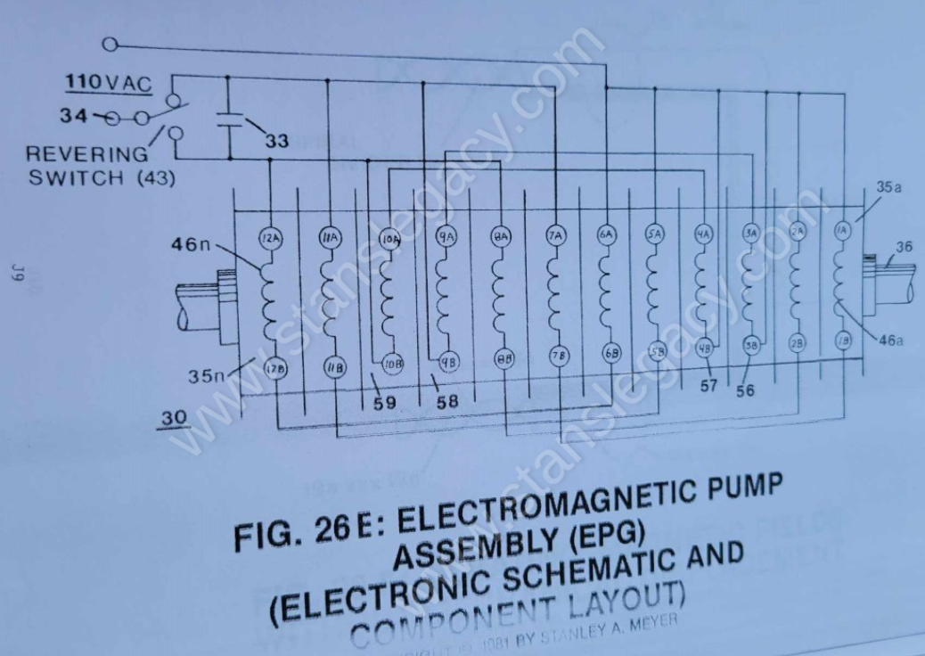
Figure (26E)
Ele Embl Y Ass Hemat
How it is written
- (26E) 6×
- (43 of Figure 26E) 1×
Drawings 1
-
Captioned as this figure · ELECTRICAL PARTICLE GENERATOR
On this figure 10
- 3 Fluid-Medium
- 30 Stator Assembly
- 33 Capacitor
- 35 Stator Assembly
- 36 Tubular Pathway
- 38 Magnetic Sweeping Field
- 46 Coil-Bobbin
- 47 Coil-Bobbin
- 48 Magnetic "Shunt" Assembly
- 54 Fluid-Mass Movement
Where it is named · 7
ELECTRICAL PARTICLE GENERATOR 7×
-
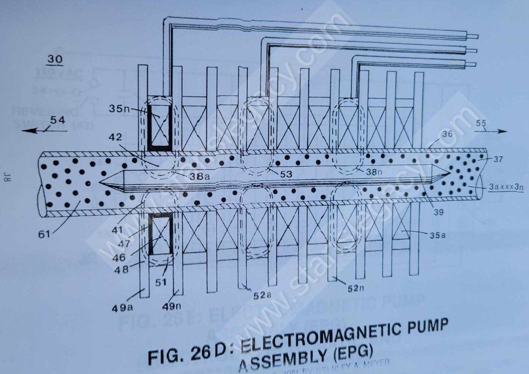
A simple mechanical switching (43 of Figure 26E) reverses the sweep of fields (38a xxx 38n) and moves the direction of fluid-medium (3) travel.
-
A simple mechanical switching (43 of Figure 26E) reverses the sweep of fields (38a xxx 38n) and moves the direction of fluid-medium (3) travel.
-
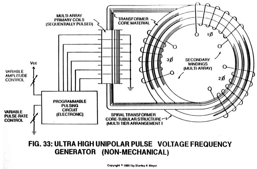
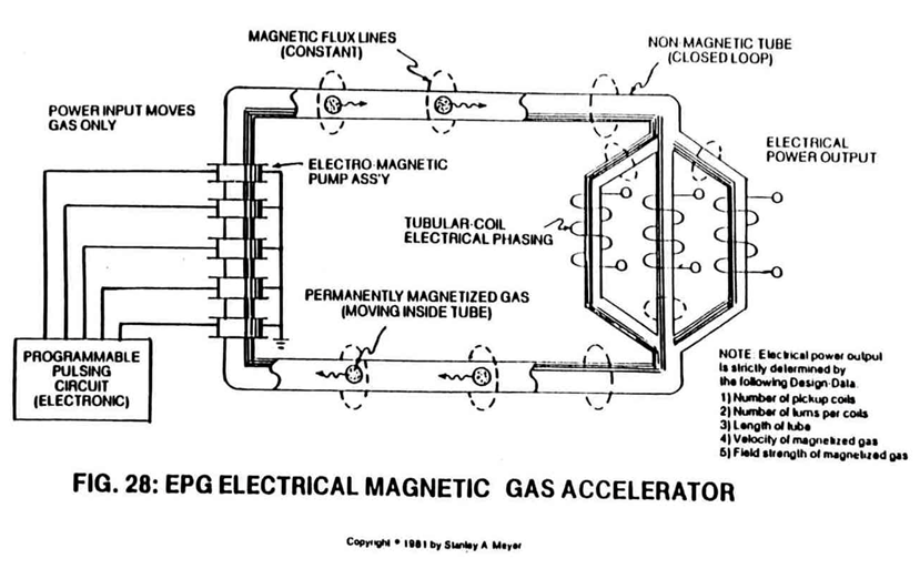
Said pulse circuit (35) is now placed end-to-end (35a xxx 35n) to said coil circuit assembly (30) for magnetic force, as illustrated in Figure 26E and Figure 28 and Figure 33.
-
Wiring of said coils (46a xxx 46n) in proper sequence (see wiring schematic Figure 26E) with said capacitor (33) produces a sweeping magnetic wave (38a xxx 38n) across said fluid-mass (3), thus allowing said fluid-mass movement (54).
-
Coil-arrangement as to Electrical Hookup (56/57 and 58/59) of Figure 26E provides temporary "Breaking Power" during switching operations.