Figure (33)
Figure (33)
How it is written
- (33) 12× with (33) Capacitor
- (30 of Figure 28 as to Figure 33) 2× with Figure (28) EPG Electrical Magnetic Gas Accelerator C
- (26 of Figure 33) 1× with (26) Pickup coil-array phasing
- (8 of Figure 33) 1× with (8) Non-Magnetic Tubular Pathway
Drawings 3
-
Carries this number · ELECTRICAL PARTICLE GENERATOR
-
Carries this number · ELECTRICAL PARTICLE GENERATOR
-
Carries this number · ELECTRICAL PARTICLE GENERATOR
On this figure 9
- 1 Tubular Pathway
- 2 Coil-Array
- 3 Fluid-Medium
- 8 Non-Magnetic Tubular Pathway
- 11 Magnetic Field
- 26 Pickup coil-array phasing
- 27 Unidirectional pulsing
- 28 Unidirectional pulsing
- 34 Power Source
Where it is named · 16
ELECTRICAL PARTICLE GENERATOR 16×
-
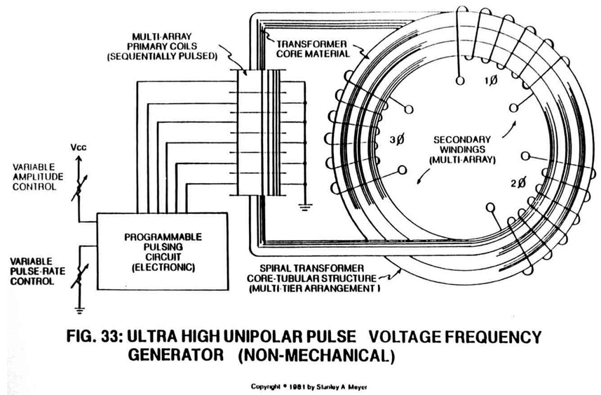
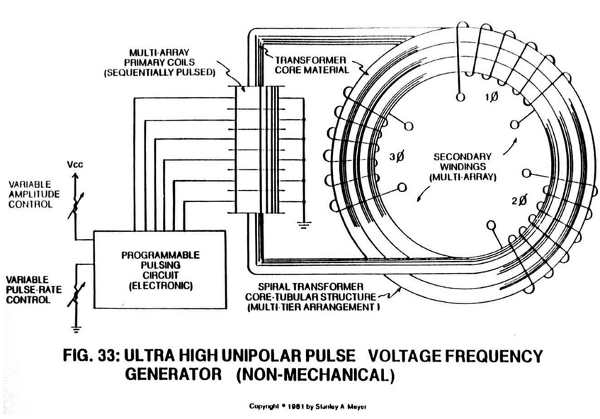
Said tubular pathway (1) can be extended into a spiral configuration (8) of Figure 33.
-
Said pickup coil (2) is placed around said spiral pathway (8) of Figure 33 to form a coil-array (2a xxx 2n).
-
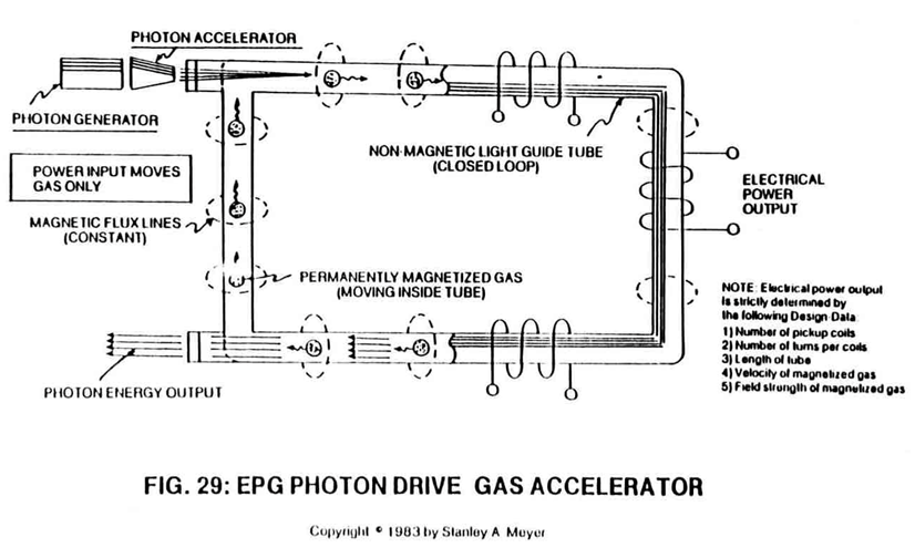
Electromagnetic Pump Assembly (30 of Figure 28 as to Figure 33) moves said fluid-medium (3) by way of electromagnetic deflection, see Figure 26F.
-
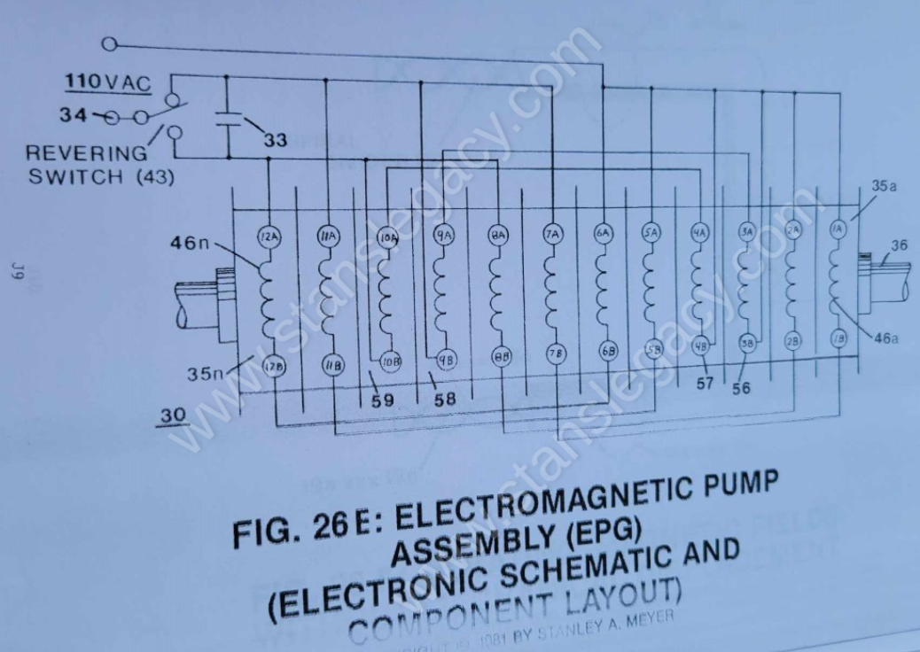
Electromagnetic Pump Assembly (30 of Figure 28 as to Figure 33) is energized by a variable AC electrical power source (34).
-
… d with said permanently magnetized material (3), said pickup coil-array (2a xxx 2n) is electrically energized to produce an electromagnetic field that completely surrounds said tubular pathway (8) of Figure 33, exposing said magnetic material (3) to said electromagnetic field... …
-
The magnetic pulsing process simply spins the dyne-axis of said particles (3a xxx 3n) to oscillate and attenuate a permanent magnetic field (4/11 as to 17/18), as illustrated in Figure 30 as to Figure 26 through Figure 33.
-
To increase said magnetic flux lines (11a xxx 11n) still further, said pathway (1) is now spiraled (8 of Figure 33) (in spaced relationship to each other) inside said pickup coil-array (2a xxx 2n), as illustrated in Figure 33 as to cross-sectional drawing titled "Multi-tubular array"of Figure 28A.
-
To increase said magnetic flux lines (11a xxx 11n) still further, said pathway (1) is now spiraled (8 of Figure 33) (in spaced relationship to each other) inside said pickup coil-array (2a xxx 2n), as illustrated in Figure 33 as to cross-sectional drawing titled "Multi-tubular array"of Figure 28A.
-
To increase said magnetic flux lines (11a xxx 11n) still further, said pathway (1) is now spiraled (8 of Figure 33) (in spaced relationship to each other) inside said pickup coil-array (2a xxx 2n), as illustrated in Figure 33 as to cross-sectional drawing titled "Multi-tubular array"of Figure 28A.
-
Electrical power output phasing (26 of Figure 33) is accomplished by simply wrapping said pickup coil (2) in opposite direction: Right-hand Movement (27) and/or Left-hand Movement (28).
-
To help minimize opposition to the movement of said magnetic fluid-medium during power on-stage, said pickup coil array (2a xxx 2n) of Figure 33 as to Figure 26F is placed and aligned end-to-end around said pathway (8a xxx 8n) for the purpose of coupling and forming a single and continuous magnetic field (31) or any type of electromagnetic fi …
-
The linear motion of said moving fluid-medium (3a xxx 3n) through the stator assembly (30) is shown in Figure 26A to Figure 33F of Figure 26B which is essentially a series of coils as stator assembly (30) which is essentially a series of coils as stator assembly (35a xxx 35n) of Figure 26C as to Figure 26 and Figure 33.
-
Said pulse circuit (35) is now placed end-to-end (35a xxx 35n) to said coil circuit assembly (30) for magnetic force, as illustrated in Figure 26E and Figure 28 and Figure 33.