(2) · also written as a run, 2a xxx 2n
Coil-Array
Also written pickup coil-array · pickup coils · coils · pickup coil · Balance-Phasing · pickup windings · coil array · wire-coil
Where it is first named
Wrap a wire-coil (2) and/or coil-array (2a xxx 2n) around one end of said non-magnetic tube (1) to comply with Maxwell/Faraday Laws of Inductance.
How it is written
- (2a xxx 2n) 17×
- (2) 4×
- (2 xxx 2n) 1×
- (equal magnetic field strength between said pickup coil-array 2a xxx 2n) 1×
2a xxx 2n is Meyer's shorthand for a run of the same thing: 2a is the first, 2n the last, and the x's stand for however many lie between. Every stage of the run is this one numeral.
Drawings 6
-
Carries this number · ELECTRICAL PARTICLE GENERATOR
-
The figure it sits on · ELECTRICAL PARTICLE GENERATOR
-
Pulse-frequency electrical output (23 of Figure 30 as to Figure 27) is strictly determined by the pulse-rate of said orientation coils (12/13). · ELECTRICAL PARTICLE GENERATOR
-
When EMF field (31) is formed, said pulsating magnetic field (29) forming concentric ring (29) is turned off (switched off). · ELECTRICAL PARTICLE GENERATOR
-
The figure it sits on · ELECTRICAL PARTICLE GENERATOR
-
The figure it sits on · ELECTRICAL PARTICLE GENERATOR
Where it is named · 23
ELECTRICAL PARTICLE GENERATOR 23×
-
wire-coil (2)
Wrap a wire-coil (2) and/or coil-array (2a xxx 2n) around one end of said non-magnetic tube (1) to comply with Maxwell/Faraday Laws of Inductance.
-
coil-array (2a xxx 2n)
Wrap a wire-coil (2) and/or coil-array (2a xxx 2n) around one end of said non-magnetic tube (1) to comply with Maxwell/Faraday Laws of Inductance.
-
pickup coil (2)
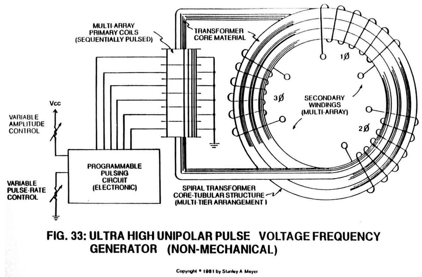
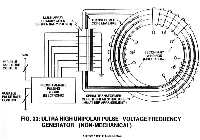
Said pickup coil (2) is placed around said spiral pathway (8) of Figure 33 to form a coil-array (2a xxx 2n).
-
coil-array (2a xxx 2n)
Said pickup coil (2) is placed around said spiral pathway (8) of Figure 33 to form a coil-array (2a xxx 2n).
-
pickup coils (2)
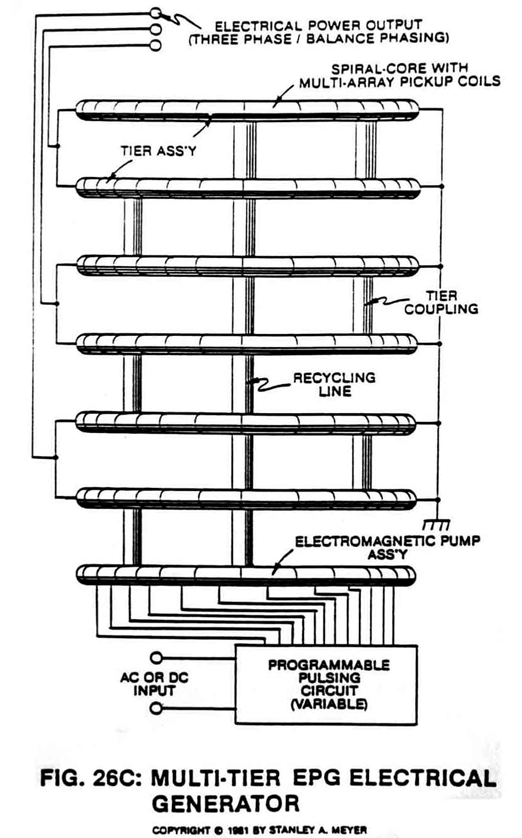
Said Particle Accelerator Assembly (10) causes and propels a permanent magnetic fluid-medium (3 of Figure 26) (liquid slurry or gases) to move toward, through, and beyond said pickup coils (2) for recycling, as illustrated in Figure 26.
-
pickup coil-array (2a xxx 2n)
Once said tubular pathway (1) as to (8) is completely filled with said permanently magnetized material (3), said pickup coil-array (2a xxx 2n) is electrically energized to produce an electromagnetic field that completely surrounds said tubular pathway (8) of Figure 33, exposing said magnetic material (3) to said electromagnetic field... …
-
coil-array (2a xxx 2n)
Said longitudinal field (4) remains after said coil-array (2a xxx 2n) is de-energized.
-
pickup coil-array (2a xxx 2n)
By attenuating or varying power input to said power drive systems (20 and/or 30) likewise varies the recycling speed or velocity of said magnetic field (4) moving toward, through, and beyond said pickup coil-array (2a xxx 2n)... moving onward to and through said Power Drive Assembly (20 and/or 30) once again for continued field recycling.
-
pickup coil-array (2a xxx 2n)
… ivider (9) of Figure 26F is now inserted into said tubular pathway (1) leading away from and connecting said Power Drive System (20/30), said Spiral Divider (9) passing through said pickup coil-array (2a xxx 2n), said Spiral Divider (9) terminating at and not passing through said Power Drive System (20/30), as shown in Figure (26F) as to Figures (26, 28, and 33).
-
pickup coil-array (2a xxx 2n)
To pulsate or vary said rotational field (11) moving in a linear direction (4), Dual-Orientational coils (12/13 of Figure 27) are now inserted into said tubular pathway on opposite side of Electromechanical Drive System (20), away from said pickup coil-array (2a xxx 2n), as illustrated in Figure (27) as to Figure 30.
-
coil-array (2a xxx 2n)
In both cases, said reforming magnetic wave-forms (17a xxx 17n and/or 18a xxx 18n) are oscillating inside said coil-array (2a xxx 2n)... producing electrical energy.
-
pickup coils (2a xxx 2n)
Transformer interaction (magnetic field coupling) between said Orientation Coils (12/13) and said pickup coils (2a xxx 2n) can "NOT" occur since said particles (3a xxx 3n) are permanently magnetized.
-
pickup coil-array (2a xxx 2n)
To move more magnetic flux lines through said pickup coil-array (2a xxx 2n) while keeping said particle (3a xxx 3n) velocity constant, said Spiral Divider (9) of Figure 26F is now subdivided into many pathway channels (19a xxx 19n), as illustrated in Figure 26A sub-titled "Rotational Deflection."
-
coil-array (2a xxx 2n)
To increase said magnetic flux lines (11a xxx 11n) still further, said pathway (1) is now spiraled (8 of Figure 33) (in spaced relationship to each other) inside said pickup coil-array (2a xxx 2n), as illustrated in Figure 33 as to cross-sectional drawing titled "Multi-tubular array"of Figure 28A.
-
The greater number of spiral-turns (8a xxx 8n) the greater number of right-hand lines transverses said pickup coil array (2a xxx 2n) during pulse-form stage.
-
pickup coil (2)
Electrical power output phasing (26 of Figure 33) is accomplished by simply wrapping said pickup coil (2) in opposite direction: Right-hand Movement (27) and/or Left-hand Movement (28).
-
Balance-Phasing (equal magnetic field strength between said pickup coil-array 2a xxx 2n)
--- Balance-Phasing (equal magnetic field strength between said pickup coil-array 2a xxx 2n) is automatic since particle velocity (4) remains constant while passing through said close-loop tubular pathway (1).
-
coils (2a xxx 2n)
Series to parallel hookup of said coils (2a xxx 2n) determines amp draw as to applied voltage. Power Output = Amps x Voltage.
-
coil-array (2a xxx 2n)
The number of tubular-legs (8a xxx 8n) spiraled inside said pickup coil-array (2a xxx 2n). The number of multi-rotational fields (11a xxx 11n) formed per turns of tubular legs (8a xxx 8n).
-
coil array (2a xxx 2n)
To help minimize opposition to the movement of said magnetic fluid-medium during power on-stage, said pickup coil array (2a xxx 2n) of Figure 33 as to Figure 26F is placed and aligned end-to-end around said pathway (8a xxx 8n) for the purpose of coupling and forming a single and continuous magnetic field (31) or any type of elect …
-
pickup coil-array (2a xxx 2n)
… ng a single and continuous magnetic field (31) or any type of electromagnetic field emanating from said pickup coil-array (during duty loading) is wrapped and positioned around said pickup coil-array (2a xxx 2n)... forming a concentric magnetic ring (31) around said pickup coil-array (12/13) as illustrated in Figure 26A sub-titled "Balancing Fields."